Quote:
Originally Posted by DMGRS

They are a little dimmer than the original item, yes. I found mine a little dim at first, but soon got used to it
|
Maybe my poor eyesight, but I simply couldn't discern what was on the screen. Better in dull light/at night, but in normal daylight I had no idea what was showing.
Quote:
- also, it's likely the original LEDs can be replaced for higher power items by Klarzy or Phil-T4 if needed. 
|
I checked that using a selection of amber LED types to compare brightness at the normal forward voltage for this colour. The MG7 LEDs are as bright as they come. I decided this wasn't the way to do it for amber backlighting. Blue LEDs presumably emit more light at the same voltage, but I don't want blue.
I think the method used in the MGR screen is better. The MG7 uses two sets of three LEDs directed into the left and right edges of a plastic slab in the manner of a light guide. The slab is 'frosted' internally with particles that disperse the light and so the slab 'illuminates'. It's rather inefficient so most of the light is wasted. I decided to take the bull by the horns and make a backlight like the MGR one.
Quote:
Originally Posted by andre372
Pictures please? I've put mine on the shelf waiting for an upgrade exactly like that.
|
I may post some later. I doubt many people will want to go down this particular road.
The unit is still on the bench after weeks of on-off effort to improve the screen visibility in daylight. I'm in no rush, but the reason I bought it was for the visual quality of the screen. I was admittedly disappointed with the MG7 unit when I installed it in my car. Others may well have got better results, but unless I can make it at least as bright as my standard box, I won't fit it. Anyway, after stripping down and seeing how the MGR one works, I decided to make a direct backlight.
The MGR unit uses a line of twelve LEDs behind a 'slab' of orange plastic. This is translucent and is in fact luminescent. In UV light it glows bright orange. So, with orange LEDs behind, it actually 'glows' quite evenly. I'd say that's the crux to good backlighting and explains why the Chinese did it the way they did. Even light distribution across the full slab.
I looked for some similar plastic, but so far have only found transparent orange perspex. The plastics supplier described it as translucent, so obviously don't know the difference. The bigger issue is how to fit enough LEDs behind it. I dabbled with home made circuit boards in my younger days so had a go with that. You can get all you need on eBay/Maplins/etc. and there are good the tutorials from Instructables/YouTube/etc. It's easy enough with some practice but I wasted quite a lot of copper clad board and the other stuff you need. If you're not into DIY or hobby electrics, my advice is to cut your losses now and don't even try.
Anyway, there's just enough clear space under the LCD unit to slot in a circuit board with however many LEDs and resistors you want to use. You have to power these independently of the aircon box, so an ignition switched supply is needed. I initially made a board with ten LEDs (in two rows of five), but the light distribution was patchy. Also remember the MG7 plastic slab is not illuminated from the rear, so the white support frame is solid across its full rear surface. With my idea, the middle area has to be cut out so it's backless (yikes! there's no going back after this!). The new slab sits in the frame but supported around the edges.
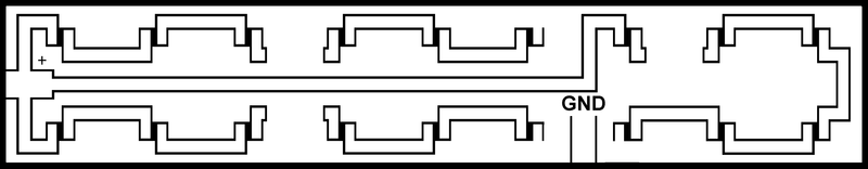
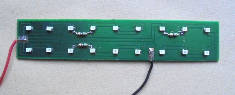
You can check the LED control resistor values using a LED calculator and the supplier's specs. There are dozens on the Internet. My current design has eighteen amber 3528 (PLCC-2) LEDs in two rows making a grid of 12-15mm squares. The most efficient (coolest running) circuit is to use six LEDs in series with a 56ohm resistor. There are three of these series connected in parallel. Any other design will create more heat from the resistors.
So as it stands, I have my homemade backlight stuck to the main board with double sided foam tape. This sits under the light dispersing slab. The slab is the 3mm thick orange perspex with a stick-on frosted film each side. On top of that sits the white plastic sheet as per MG7 original. This whole thing sits in the modfied support frame with the LCD unit on top of that. The whole lot is held solid to the board with the sheet metal cage.
Connecting it up to the car confirms I'm getting where I want to be. I've not yet installed it properly because I'll be using a 500mA in-line fuse from the switched supply for the backlightand I'm waiting for some small scotchlocks.
This is the current circuit board. The first attempt used ten LEDs, each with a 560ohm SMD resistor. It also got too hot. I really couldn't be bothered with the tiny stuff this time.
So, it's a big job and not for the faint hearted. Be prepared to ruin the controller or leave it well alone.
I take no responsibility for anyone else's disaster!
TC
PS: This is my hand drawn pcb stencil if anyone fancies a go.