
|
|
|
|
|
|
||
|
|
||
 1st August 2007, 21:27
|
#51 | |
|
Avid contributor
Rover 75 Join Date: Mar 2007
Location: Almere
Posts: 193
Thanks: 0
Thanked 0 Times in 0 Posts
|
Quote:
I succeeded in all the connections exept these ones. Do you have experience how to fix this. I made an attachment of the electrical circuit diagram in wich they occur. Interface K-bus (V106): C0395-10 to C1245-2 speed dependant volume signal C0395-17 to C1245-5 not used? C1245-3 to A211 ? C1245-6 to A165 earth I believe CD auto changer (F102): C0941-6 to C0830-1 CD audio left + C0941-1 to C0830-2 CD audio right + C0941-7 to C0830-6 CD audio left C0941-2 to C0830-7 CD audio left C0941-8 to A165 earth C0941-5 to C0295-16 header (K106) C0941-10 to C0295-4 header (K106) Monitor-bord (D185): C0816 to A172 ? What I have now tested and working is: - radio - televison - navigation The High Line is fully operational exept for the steering wheel controls and the CD changer. BTW Keith, my english is rather poor and I don't know what you mean by "iirc" I must thank you for the little leads you gave me. It helped me a lot thinking about what I did wrong. So I checked almost every diagram from Low LIne to High Line. But this amateur is very happy  now that the High Line is alive after three days hard work. The Low Line has become more and more history now that the High Line is alive after three days hard work. The Low Line has become more and more historyHope you can help me out with this. Regards Ralph  |
|

|

|
|
1st August 2007, 21:52
|
#52 |
|
This is my second home
ZT400 Join Date: Oct 2006
Location: Ellesmere
Posts: 5,948
Thanks: 0
Thanked 43 Times in 29 Posts
|
The CD changer has seven wires four are audio L & R + & - but I don't know which so that needs trial an error the other three are +12V Ground and K bus
For the steering wheel controls have you got the Interface box  |
|
|
|
|
1st August 2007, 22:46
|
#53 | |
|
*
Rover 75 FaceLift Tourer CDTi 170BHP Auto ConnSE 2005 Model Starlight Silver Join Date: Nov 2006
Location: Abergele
Posts: 28,735
Thanks: 0
Thanked 6 Times in 5 Posts
|
Quote:
or If I Recall Correctly or Image and Identity Research Collective (not usually this in our Context) Last edited by JohnDotCom; 1st August 2007 at 22:53.. Reason: spelling |
|
|
|
|
|
1st August 2007, 22:49
|
#54 | |
|
Avid contributor
Rover 75 Join Date: Mar 2007
Location: Almere
Posts: 193
Thanks: 0
Thanked 0 Times in 0 Posts
|
Quote:
Yes I do have it, partnumber YWQ100031 brandnew from Xparts. But I don't have the bracket for it yet (minor detail) The problem is that my CD changer is in the glove box with indeed seven wires wich all end in my old connector C0983 of the low line. Not compatible with connector C0830 from the the radio wich is in the boot and there is only one possibility to connect the CD changer on it by C0830 wich I don't have. The four wires left and right + & - I can understand and solve the problem maybe by lengthen it to the boot. But the other three on the diagram are connected to the header (2x) and monitor bord (1x) wich I can't follow. Both connectors from the header (C0295) and CD changer (C0941) are not in included within the manual. BTW I left my old loom of the low line in the car. It was to much work to get rid of it because of all its sideway connections. Shame on me  but no one will notice that. I might want to use some existing wires from it wich leads all to the boot for the C0830 connection but I don't dare to do it, because I will damage a part of it. but no one will notice that. I might want to use some existing wires from it wich leads all to the boot for the C0830 connection but I don't dare to do it, because I will damage a part of it.Any suggestion? Here are some pictures of the current status: Back to school  The Interface K-bus with cable  TV module didn't fit on its place because of my LPG tank in the spare wheel room so I had to mount it here 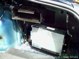 Bracket for the radio module in place  Peeling off my existing GPS antenna cable from the old Low Line loom  Leading the loom from the boot sideways to the dash    At last I reached the front  Later on I will post some piccys when it's finished. That's all for now fooks! :lol: Last edited by damydyo1; 1st August 2007 at 23:49.. |
|
|
|
|
|
4th August 2007, 20:00
|
#55 |
|
Avid contributor
Rover 75 Join Date: Mar 2007
Location: Almere
Posts: 193
Thanks: 0
Thanked 0 Times in 0 Posts
|
It has been worth all effort, but I had some major problems in the beginning.
At first nothing worked at all when I connected my new high loom to the iso adapted loom wich on their turn were connected to the iso connectors in my dash. If you have not all the functions provided in your iso then you should do the same as I did. I connected my new loom with the C0395 directly on the C0981. After that my high line started to breath with: - radio - TV - navigation The next thing I had to work out was connecting my CD changer wich is in the glove box. The kufatec connectors they gave me, weren't right. So I had to make a rather unprofessional solution. This is the CD changer plug beneath my glove box  They end all up to C0983 (blue) in my dash. There are 7 wires. I put 7 pins into it and 4 of them I had to lead to C0830 at the back of my radio unit.  Having the electrical diagram at hand I used a 4 wire colored cable for 2x audio left (+/-) and 2x audio right (+/-) The other three I put one on 12 V permanent feed, one on earth and one was for the K-bus connection    Having done that I had audio from my CD changer. Not at first trial because I put one pin wrong, but that was solved after I checked everything. Now I had to mount the interface K-bus behind the head unit, but some of you know I didnt had the specific bracket for it so I fixed it with tie rips.  The connector for the K-bus I got from Kufatec of which they said was for my CD changer. Anyway, I connected the four wires as the electrical diagram showed to C0082 under the steering column   The other ends I connected to earth from the monitor-bord and as leading K-bus wire foor all components and header. Here is where I went wrong I think, because I put it on a WRY colored wire from C0981  I was ready to organize all the cables in the dash and at first it looked rather chaotic but all went well with tie rips and tape.  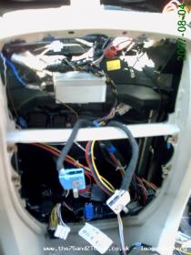  Closing my dash I worried about the functionality of the K-bus. would it work? And what about the rotary coupler, switch reverse and ECU-ABS? But as you all can see these were the results as I finished the dash. Radio functions OK 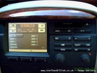 Tape functions OK  CD functions OK  Navigation OK  TV no signal because of the missing analog signal in Holland, but seems to work I hope in foreign countries 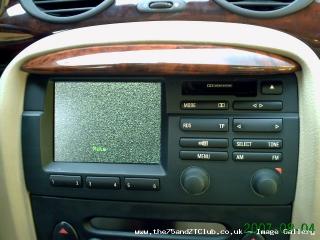 Later on I finished everything with the covers in front and in the boot 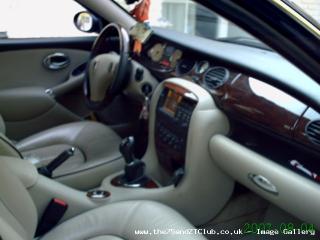   My Low Line (Symphony with SatNav and MKII GPS) set is now history and are for sale. The loom is still in the car and I have to figure out how to get rid of it. It is a lot work to get it out of the car and sell it completely with the Low Line set.  After the first test drive everything was in fine order, only for the K-bus where I was afraid for. The speed dependant volume signal did not respond and the remote controls also. Maybe someone has a suggestion? Also the connection for the switch-reverse and ECU-ABS are important ones. You will find them on the six pins connector C0982 wich you realy have to look for in the dash as shown at the picture below.  I would like to end with: Don't try this at home. Miracles take more time. But I'm glad the system works for 95% and maybe this thread has been a little help for the one who didn't dare to do this but might consider it over. I think some of you would give it a try regarding the 1580 views on this thread....... It has been a pleasure to inform all of you. Special credit goes to Johndotcom and Keith who made it possible for me to do this! Till the following project. Cheers Ralph Last edited by damydyo1; 5th August 2007 at 21:25.. |
|
|
|
|
11th September 2007, 22:16
|
#56 |
|
Avid contributor
Rover 75 Join Date: Mar 2007
Location: Almere
Posts: 193
Thanks: 0
Thanked 0 Times in 0 Posts
|
Hello guys,
It's been a while but I could still need some help or any reply on what I did wrong with the connection on my K-bus. Everything works exept: - remote controle audio steering wheel - speed volume Regards Ralph |
|
|
|
|
11th September 2007, 22:39
|
#57 |
|
Moderator

MG-ZTT Join Date: Mar 2007
Location: Ware, Herts
Posts: 19,798
Thanks: 161
Thanked 1,249 Times in 1,036 Posts
|
Well done Ralph.
I'm about to embark on a similar project, except I've got the original loom............
__________________
David  Impecunity is the mother of ingenuity Useful how to's for common problems Car Of The Month Jan 2014 [SatNav Power Down] [Coolant Level] [SatNav Repair] [Diesel Non Starting] [Paint Codes] [Rear Light Seals] [Reversing Light Switch] [Bleeding Brakes][Sunroof Drain] [Early ZT's][Instrument Pack Diagnostics][ATC Diagnostics] |
|
|
|
|
13th September 2007, 17:47
|
#58 |
|
Avid contributor
Rover 75 Join Date: Mar 2007
Location: Almere
Posts: 193
Thanks: 0
Thanked 0 Times in 0 Posts
|
Hello David,
Did you get the loom new or from a breaker. I would like to see the original loom. Do you have some piccy's for me and did you had any progress until now? Regards Ralph |
|
|
|
|
13th September 2007, 18:54
|
#59 | |
|
Moderator
MG-ZTT Join Date: Mar 2007
Location: Ware, Herts
Posts: 19,798
Thanks: 161
Thanked 1,249 Times in 1,036 Posts
|
Quote:
I've managed to get a complete set up from a 2000 car. Let me know what pictures you want and I'll take them and post them up.
__________________
David Impecunity is the mother of ingenuity Useful how to's for common problems Car Of The Month Jan 2014 [SatNav Power Down] [Coolant Level] [SatNav Repair] [Diesel Non Starting] [Paint Codes] [Rear Light Seals] [Reversing Light Switch] [Bleeding Brakes][Sunroof Drain] [Early ZT's][Instrument Pack Diagnostics][ATC Diagnostics] |
|
|
|
|
|
13th September 2007, 20:36
|
#60 | |
|
Avid contributor
Rover 75 Join Date: Mar 2007
Location: Almere
Posts: 193
Thanks: 0
Thanked 0 Times in 0 Posts
|
Quote:
Please some visuals of: - the whole loom - separate connectors to: * Head unit * Interface K-bus * CD changer * Radio module * TV-module * antenna"s * GPS module * the two separate wires to C0982 for "ECU-ABS" and "Switch Reverse" Was this thread usefull for you David, or do you have some questions or suggestions, because I noticed a lot of members have read it but you are the first who is actualy starting it all up? cheers Ralph Last edited by damydyo1; 13th September 2007 at 20:42.. |
|
|
|
|
 |
|
|


 Linear Mode

