
|
|
|
|
|
|
||
|
|
||
 20th March 2012, 11:43
|
#1 |
|
This is my second home
75 Contemporary SE Mk II 2004 Man. Sal. CDTi 135ps, FBH on red diesel, WinCE6 DD Join Date: May 2010
Location: Leeds
Posts: 17,273
Thanks: 2,160
Thanked 2,061 Times in 1,586 Posts
|
A Cheaper alternative timer control - provided from an idea of BrianW
This project is based upon liberating the timer module from a low cost 13amp plug in digital timer unit from Wilkinsons. 7 day 24 hour, offering 10 on/off's over the period, with auto and manual on or off overide. So probably more capable than the OEM offering. This one - http://www.wilkinsonplus.com/electri...49VztZhg%3D%3D £5.97. I would suggest a good place to mount the timer would be in the centre console, under the lid - which is the standard location for the OEM timer. The easiest cable route for which is - from the FBH, back to the bulkhead, over to the drivers side, where there is a rubber bung each side of the plenum which can be pierced to let the cable through. From there (just above the accelerator pedal), it can be routed across to the centre console and back to the lidded compartment between the seats.  The plug in timer opened up. Only the module on the right, plus the 1.2v rechargeable cell - the green component in the middle of the photo are needed for the project, everything else is surplus.  Here is a copy of the instructions, so you know what it is capable of (Use Ctrl and + to zoom in to read).   There is just one red LED indicator on the unit and the LED lights up to show the FBH is enabled, it provides no feedback as to whether the FBH is actually running or not, just that the timer says go. I would suggest it might be a very good idea to add the 'LED2' in a prominant place visible from the driving seat. 'LED2' is very simple circuit detailed in my FBH How To, linked to in my sig below. It basically flashes everytime the fuel pump is fired and gives absolute confirmation that the FBH is running and how hard it is working. The colours marked on the diagram, are the colours of LAN cable core wire markings. whi/bro is the white wire wrapped around the brown. The other four colours used are brown; blue, orange and green. LAN cable is small, quite flexible so easy to install and has much more than enough current capability for the mA's needed. Note- The two resistors tapped onto the FBH's 12v supply should be located as close as possible to where the 12v supply is tapped off the FBH. The reason for this is to limit any fault current on the LAN cable to just a few milliamps. The FBH's 12v is fused at 15amp's and you certainly would not want 15amps flowing through a small LAN wire should a fault in your wiring occur. 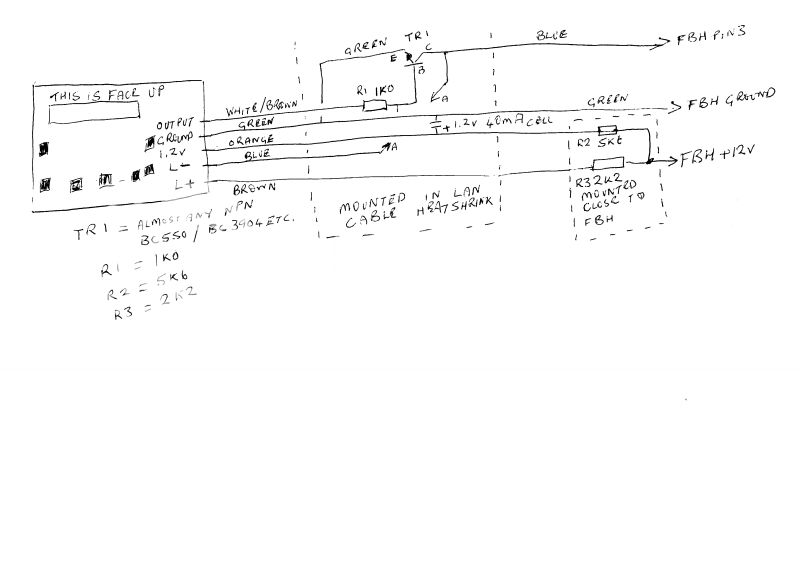 The back of the timer button panel.  The timer PCB, with 4 pair LAN cable connected. Note the yellow tape over the Random operation button contacts- You would not want to be able to set the FBH to come on at random times, so best disable the button with tape.  LAN cable connected and a short section of outer of the cable stripped in readiness to start inserting components. I made the stripped section about 9" away from the timer, so the section with components in it can be pushed below the armrest compartment via a small hole, so all that shows in the compartment is the timer module control panel.  1.2v cell connected into the middle of the LAN cabling. Once all of these components are in place, tested and working, the exposed cable and components can be covered with some heatshrink.  Additional components integrated into the LAN cabling.  Another view from a different angle.  Completed and on test, awaiting heatshrink.  Back of timer module, wires and the crystal given an extra bit of stability with a bit of hot melt glue.  Heatshrinked, retested and ready to install. After testing various methods, I found the best way to do the heatshrink was to slip the sleaving over the components, then force hot melt glue down inside. This reinforces the heatshrink, stabilises the components and the heatshrink shrinks down good and tight with not gaps. Just before fitting the heatshrink, add a bit of tape between component leads where ever there might be a possibilty of the coming into contact.  Packet of ciggies to show just how tiny this little unit is and the extra component section hidden in the heatshrink.  I have now revised the cost to £25 for a ready built and tested unit with cable, already to be installed. Just feed the cable in from the armrest box, to the FBH and connect three wires to the FBH. It is a bit of a tricky job, but you are most welcome to use the above information to build one yourself.
__________________
Harry How To's and items I offer for free, or just to cover the cost of my expenses... http://www.the75andztclub.co.uk/foru...40#post1764540 Fix a poor handbrake; DIY ABS diagnostic unit; Loan of the spanner needed to change the CDT belts; free OBD diagnostics +MAF; Correct Bosch MAF cheap; DVB-T install in an ex-hi-line system; DD install with a HK amp; FBH servicing. I've taken a vow of poverty. To annoy me, send money. Last edited by HarryM1BYT; 20th March 2012 at 22:12.. |

|

|
|
20th March 2012, 12:04
|
#2 |
|
Regular poster
Rover 75 2.0cdt conn Tourer (55 Plate) Join Date: Jun 2011
Location: Stockport
Posts: 59
Thanks: 0
Thanked 0 Times in 0 Posts
|
Hi Harry, When you succeed ,please put me down for one.Alec
|
|
|
|
|
20th March 2012, 12:11
|
#3 |
|
Loves to post
rover 75 CDTI tourer Join Date: Feb 2012
Location: swansea
Posts: 423
Thanks: 0
Thanked 1 Time in 1 Post
|
Hi,
Do you have a componets list. I can see some on the diagram. Are any salvageable from the pcb with the timer? I'm off to maplins later so I could pick up any missing bits.  John
__________________
Membership Number 1086 Mods so far Smiley number plate, L.E.D. internal lighting Pending Mods EGR Valve. 160 remap. L.E.D. sidelights. [SIGPIC][/SIGPIC] |
|
|
|
|
20th March 2012, 14:57
|
#4 | |
|
This is my second home
75 Contemporary SE Mk II 2004 Man. Sal. CDTi 135ps, FBH on red diesel, WinCE6 DD Join Date: May 2010
Location: Leeds
Posts: 17,273
Thanks: 2,160
Thanked 2,061 Times in 1,586 Posts
|
Quote:
1x 1k0Ohm, 1x 5k6Ohm, 1x 2k2Ohm and some sort of NPN transistor - BC3904/ BC550...., nothing critical about the spec., any general purpose NPN should work fine. As said it is still in the design /test phase, so things might change. I also now suggest adding the LED2 circuit which is wired between the fuel pump output and ground, located somewhere where it can be easily seen as you drive, as it is absolutely invaluable to see what the FBH is up to. For that you need 1x 3mm superbright LED and 1x 470Ohm resistor. The circuit is in my FBH how to in my sig below. Oh and 4.5m of 4 pair LAN cable (seems a lot, but that is what I measured it as).
__________________
Harry How To's and items I offer for free, or just to cover the cost of my expenses... http://www.the75andztclub.co.uk/foru...40#post1764540 Fix a poor handbrake; DIY ABS diagnostic unit; Loan of the spanner needed to change the CDT belts; free OBD diagnostics +MAF; Correct Bosch MAF cheap; DVB-T install in an ex-hi-line system; DD install with a HK amp; FBH servicing. I've taken a vow of poverty. To annoy me, send money. |
|
|
|
|
|
20th March 2012, 15:57
|
#5 |
|
Loves to post
None Join Date: Feb 2012
Location: Reading
Posts: 466
Thanks: 1
Thanked 15 Times in 15 Posts
|
I'm interested as well.
|
|
|
|
|
20th March 2012, 17:47
|
#6 |
|
This is my second home
75 Contemporary SE Mk II 2004 Man. Sal. CDTi 135ps, FBH on red diesel, WinCE6 DD Join Date: May 2010
Location: Leeds
Posts: 17,273
Thanks: 2,160
Thanked 2,061 Times in 1,586 Posts
|
As scribbled out above on the lined note paper, the circuit is now working. I have not found it necessary to install the two diodes to limit the charge voltage across the cell, so those have been omitted. Maximum voltage appearing across the cell when on charge from anywhere between 3 to 14.5v was 1.32v at around 2mA. The unit also functions happily down to an input voltage of 3v, but I understand the FBH only continues to function down to around 10v. Output to pin 3 of FBH, tested at a supply 14v shows 13.8 with the unit set to off and 0.2v with the unit set to on.
I don't want to put anyone off, you will need a bit of skill to actually install these timers - they are absolutely not a plug play in option. You will also need to source a socket pin, for pin 3 or steal a pin complete with its wire from a scrap car. The heatshrink section of the LAN cable will also be very delicate too. So great care will be needed taken when installing it. Unfortunately, I managed to break the LCD display, so the cost of an extra unit will need to be factored into the cost for you guys wanting a built up one and the whole job is taking longer than expected, so I will have to revise the cost up to £25 delivered. I also don't want to be tied up for months building these, so I'll limit this to an initial batch of just 5 units. PM me and I will then ask you for a paypal gift payment, but I will not actually accept the payment until the job is under way. I would prefer the first one went to someone with some basic electronics skills and who could get it installed and tested quickly. The idea being to check how the install goes, verify my own findings. I would also like them to advise me of how much too long the LAN cabling is, so I can trim it down to an exact length - the FBH end would need two resistors to be removed and refitted on the shorted cable end. I've just got it fully completed and the 'guinea pig', can have it for £20 - discounted for providing me with the feedback I'm looking for on the install. Here is the first one completed, but still awaiting a replacement for the LCD screen which I managed to damage. The size is much smaller than a packet of ciggarettes and is a pretty good fit for where the pukka control was designed to be fitted in the console. Note - I believe this unit may only be compatable with the more commonly found and later model of FBH, Model 98570B. To install... Drill a small hole in the base/ bottom of the centre armrest, just large enough for the cable with the black heatshrink section to pass through, control unit should then neatly cover the hole once fixed in place with double sided tape. Pass cable end through centre console towards the dash, then along dash to drivers side where there is a blank rubber bung. Make suitable hole in that, to get it into the plenum chamber and another in the bung at the otherside of the plenum, which gets it into the O/S engine compartment. From there it can be run along the clips at the back of the engine bay and round to the FBH. At the FBH, there are just three connections to be made two onto the existing wiring +12 and ground, then the third onto pin 3 of the multi-plug. Pin 3 is normally filled with a tiny bung and unused, so a pin will need to be sourced. One source would be from a scrap car, by cutting off the plug plus some cable or just the pins can be bought from an on-line specialist supplier. The timer itself provides multiple options for when the unit should switch on and off, ten completely indepedant on's and off's per week, plus days multiple choices of days when it can do the same each day, an on and an off overide off the program, plus a single button press to switch between summer and winter time - basicaly much more than is needed for your FBH timing control and much cleverer than the proper Webasto FBH time controller. Bad points - the display is quite tiny. Good points it only consumes 2ma of current whether set for on or off - so it will not discharge your car's battery It is also battery backed, so disconnecting your car's battery will not mean your having to reprogram the unit.
__________________
Harry How To's and items I offer for free, or just to cover the cost of my expenses... http://www.the75andztclub.co.uk/foru...40#post1764540 Fix a poor handbrake; DIY ABS diagnostic unit; Loan of the spanner needed to change the CDT belts; free OBD diagnostics +MAF; Correct Bosch MAF cheap; DVB-T install in an ex-hi-line system; DD install with a HK amp; FBH servicing. I've taken a vow of poverty. To annoy me, send money. Last edited by HarryM1BYT; 20th March 2012 at 22:21.. |
|
|
|
|
20th March 2012, 18:46
|
#7 |
|
Loves to post
rover 75 CDTI tourer Join Date: Feb 2012
Location: swansea
Posts: 423
Thanks: 0
Thanked 1 Time in 1 Post
|
Hi,
I haven't got the additional components yet but I have got a 3.5m lan cable. oh yeah and a working soldering iron. The lan cable I would say would be long enough. I will let you know. Going to try to put what I have together tonight. Probably won't be able to fit until the weekend. Cheers John
__________________
Membership Number 1086 Mods so far Smiley number plate, L.E.D. internal lighting Pending Mods EGR Valve. 160 remap. L.E.D. sidelights. [SIGPIC][/SIGPIC] |
|
|
|
|
20th March 2012, 19:27
|
#8 |
|
Regular poster
Rover 75 2.0cdt conn Tourer (55 Plate) Join Date: Jun 2011
Location: Stockport
Posts: 59
Thanks: 0
Thanked 0 Times in 0 Posts
|
Harry ,you've frightened me now !!!
 but still interested if it ever develops into a "plug and play" , Alec but still interested if it ever develops into a "plug and play" , Alec |
|
|
|
|
20th March 2012, 20:05
|
#9 | |
|
This is my second home
75 Contemporary SE Mk II 2004 Man. Sal. CDTi 135ps, FBH on red diesel, WinCE6 DD Join Date: May 2010
Location: Leeds
Posts: 17,273
Thanks: 2,160
Thanked 2,061 Times in 1,586 Posts
|
Quote:
Could you get me an exact measurement of the LAN cable length needed please and the route you take please? The problem is there are components mounted at each end and I want to try to avoid people having to resolder because the cable is too long. Best way is start with a known exact length, then see how much you end up chopping off of the FBH end. Oh - and be very, very careful with that display  Undo the two screws, then the PCB is just held in with three tags in the case, at each edge. When it comes to the extra components, inside the heatshrink - The best way is fit some heatshrink over them, then force the nozzle of an hot melt glue gun into the heatshrink and squeeze. As the hot melt glue goes in, it fills the space up around the components and as it does that the heatshrink contracts around everything holding it all firm. Put a bit of tape between bare leads, where they are likely to be shorted, before you proceed to the heatshrink stage - pictures to follow soon and a better circuit diagram. I just opened up the timer unit, to solder my LAN cable directly onto the board, put the half with the display in it on the bench - then the LAN cable caught it and flipped it across the floor 
__________________
Harry How To's and items I offer for free, or just to cover the cost of my expenses... http://www.the75andztclub.co.uk/foru...40#post1764540 Fix a poor handbrake; DIY ABS diagnostic unit; Loan of the spanner needed to change the CDT belts; free OBD diagnostics +MAF; Correct Bosch MAF cheap; DVB-T install in an ex-hi-line system; DD install with a HK amp; FBH servicing. I've taken a vow of poverty. To annoy me, send money. |
|
|
|
|
|
20th March 2012, 20:11
|
#10 | |
|
This is my second home
75 Contemporary SE Mk II 2004 Man. Sal. CDTi 135ps, FBH on red diesel, WinCE6 DD Join Date: May 2010
Location: Leeds
Posts: 17,273
Thanks: 2,160
Thanked 2,061 Times in 1,586 Posts
|
Quote:
__________________
Harry How To's and items I offer for free, or just to cover the cost of my expenses... http://www.the75andztclub.co.uk/foru...40#post1764540 Fix a poor handbrake; DIY ABS diagnostic unit; Loan of the spanner needed to change the CDT belts; free OBD diagnostics +MAF; Correct Bosch MAF cheap; DVB-T install in an ex-hi-line system; DD install with a HK amp; FBH servicing. I've taken a vow of poverty. To annoy me, send money. |
|
|
|
|
 |
|
|


 Linear Mode

