Well done Dave

Covered everything nicely there

Just to nicely summarise the guidance above, here's the list of wiring I wrote up for myself when doing the GSM mod on mine:
GSM relay:
+V: wire to 12v feed from fuse box (5amp fuse)
Negative: wire to suitable earth.
Relay 1 for FBH:
NO: wire to pin 3 on FBH.
C (or NC if labelled incorrectly on GSM):
wire to earth
Relay 2 for Heater Controls:
NO: wire to pin 13 of DPDT relay (based on the DPDT relay in the pic in post 1)
C (or NC if labelled incorrectly on GSM): wire to +12 from fusebox (5 amp fuse)
My 12 pin Double Pole Double Throw Relay (from the picture in post 1 above):
Pin 1: White/Orange wire for AC (Car side)
Pin 2: Green/White wire for AC (Car Side)
Pin 5: 12v feed from fuse box (5amp fuse)
Pin 6: 12v feed from fuse box (5amp fuse)
Pin 9: White/Orange wire for AC (AC Controls Side)
Pin 10: Green/White wire for AC (AC Controls Side)
Pin 13:
12v feed from relay 2 GSM unit terminal NO
Pin 14: Wire to Earth
12v Power Feed:
I used two fuse taps (in the pic in post 1) to power my two relays. The way they work is you remove any existing fuse from your interior fuse box, and put the fuse tap in it's place. The fuse tap has two fuse slots, 1 for the existing fuse you removed, and the second for the feed you wish to create. See picture below:

The first fuse tap i split into two feeds and wired both to the GSM relay (1 to power the relay and the other to terminal C of Relay 2.
The second fuse tap I again split into two feeds and connected it to pins 5 and 6 of the DBDT relay. You will need to use 5 amp fuses for your feeds (you will need two 5 amp fuses).
Wiring from FBH to GSM relay:
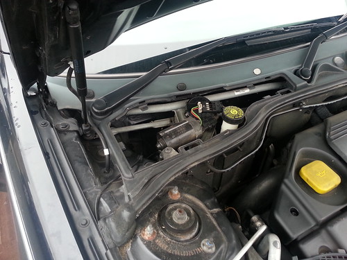
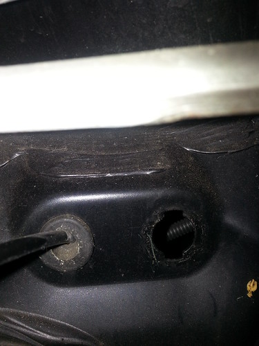
To run an wire from Pin 3 of the FBH to the GSM unit inside the car, you will need to run your wiring a long the back of the engine bay, across to the driver's side and pass it through the rubber grommit in the driver side plenum which you can see in the pics below. Once passed through here, you will be able to retrieve the wiring from the driver's side footwell after dropping down the panel above the foot pedals which is held on with 2 screws. The wire can then be passed through to the centre cubby hole.
WARNING: when wiring to pin 3 of the 6 pin plug for the FBH, make sure you remove the little blue rubber blank from the pin. You will need to use either tweezers or a needl and dont push down on the rubber blank otherwise it pushes down the plug and becomes a real pain to remove. Trust me, I found out the hard way
 Wiring:
I used 14AMP rated 0.75 thin wall cable I had left over from my cruise control retrofit, which can be purchased from ebay. See here
 http://www.ebay.co.uk/itm/50M-Roll-1...a8NlkEOCyrOqZw
My DPDT relay is placed next to the heater controls in the centre consol. When you take the heater controls out, you'll notice there is a lot of space to the left or right of where the unit goes, so I secured mine on one side.
You will need female spade connectors for the DPDT relay like these:
http://www.ebay.co.uk/itm/FEMALE-SPADE-TERMINAL-ELECTRICAL-CRIMP-WIRE-CONNECTOR-5-amp-35-amp-/251976504995?var=&hash=item3aaaf856a3:m:mKuqdvB5Uo 6kvlkxRQEDxDgI can't remember what side I used now, I simply popped down to my local private DIY store and picked the size that would fit the spades on my DPDT relay.
I placed my GSM unit in the centre cubby hole simply for easy access just in case I needed to get to it, for example to register another mobile number (the GSM will only accept texts and calls from registered numbers, this prevents those PPI nusance callers from activating your FBH). To run the cables to the GSM unit, you will need to pop up the gear surround and handbrake gaiter, and you will need to drill a hole in the bottom of your cubby hole (make sure you remove the cubby hole from the car and drill it outside). It is held in place with two torx head screws, simply remove screws and pop out.
When running the cables from the heater controls to the GSM unit in the cubby hole, make sure you keep the cables clear of the gear stick and the hand brake (wouldn't want it to get caught).
I'd also advise fitting a quick release plug like the one in the link below for the wires running to the GSM relay, which was advised to me by Dave (Duotone), to prevent shorting the relay whilst connecting or removing wires from the terminal. I did this by accident first and blew two of my fuses
You'll need a 6 pin for the GSM unit.
http://www.ebay.co.uk/itm/Tyco-AMP-E...Wsrc0SFlCqeIWw
Retrofitting Fuel Burning Heater:
I also had to retrofit the FBH itself, so for those who don't currently have a fuel burning heater fitted to their diesel and would like to fit one, here is a link to a very useful how to on servicing and fitting a fuel burning heater.
http://www.the75andztclub.co.uk/foru...d.php?t=100297
Hope these two posts covers everything you need to know to do this mod
Thanks again Dave for all your help