I've put on a few posts recently with similar questions. Ignore them all. This is the Final Question to complete my cruise control retrofit.
Jamie Welch handsomely configured my ZT with T4 this morning - thanks again.

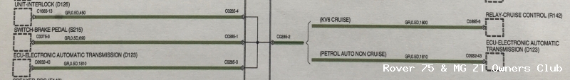
I got a clean bill of wiring health but there is a brake switch conundrum preventing it from working which I need someone's knowledge about. Please refer to the two diagrams in conjunction with the issue.
Context
• My KV6 was built without cruise and interlock
• The brake switch has all four wires connected
• Header C0285 is missing from the car. That mostly makes sense as it deals with cruise and parking sensors, none of which my car has
• The green/red (GR) wire from the brake switch pin 3 (C0775-3) is connected to the electronic auto transmission (EAT) pin 43 (C0932-43) in line with its pre-cruise state. It currently functions exactly the same as the wire from C0775-4 which controls the brakes lights i.e. power appears when the brake pedal is depressed. I do not know if it would function this way if the car was OEM-fitted with cruise as there
may be two switch types (one is referred to at Rimmers as double pole, and is shown (only once) on a RAVE wiring diagram as double pole).
• Whilst T4 confirms the brake lights functioning correctly from C0775-4, it however reports the brakes being permanently
on based on C0775-3. This is despite both pins C0775-3 and -4 behaving identically. This alone appears to be preventing cruise from working.
• Pin 6 on the cruise control relay (C0895-6) requires to be connected to C0775-3; in the absence of header C0285, I piggybacked off the EAT C0932-43 as above, to C0895-6. The GR wire colours are also consistent. I am however now doubting whether this is correct based on the attached diagrams.
Wot I need help with
• I do not know if the OEM brake switch is double-pole. It's only shown once in the entire ZT wiring diagrams as being double-pole and is not shown as such on the attached diagrams. Might this be making any difference to how pin 3 behaves - perhaps open when pin 4 is closed and vice versa?
• Should I disconnect the EAT C0932-43 from the brake switch C0775-3 now that cruise is fitted? I'm unable to interpret the diagram in that respect.
• Finally, the smaller of the two attached diagrams shows C0932-43 being connected twice to the missing C0285 (pin 2 and pin 3). Is it safe to assume that I can disconnect the brake switch C0775-3 from EAT C0932-43 altogether and instead connect it directly to the cruise relay C0895-6?
That's what my brain took me before I wrote this down, and it still arrives at the same point.
I realise wiring isn't everyone's bag but it's straightforward for others. I've always had a good knowledge but have limitations. Someone more qualified help will be hugely appreciated. Thanks in advance.
Dougie.