
|
|
|
|
|
|
||
|
|
||
 1st July 2008, 09:16
|
#1 |
|
I really should get out more.......
260 SE vin 214 ( last mark 1 260 ) Join Date: Dec 2006
Location: Lancashire
Posts: 2,009
Thanks: 1
Thanked 8 Times in 4 Posts
|
this how to applies to the fitment of the MGR detachable towing bracket and electrics kit, however sections will be applicable to generic towing brackets.
For reference some part numbers are included, however these should be confirmed with the supplier at the time of ordering TOWBAR DETACHABLE VUB003070 TOWBAR FIXED VUB003060 LINK KIT YMZ000120 FROM VIN 24554 TO 03MY279844 YMZ000150 FROM VIN 279884 TOWING ELECTRIC KIT 12N/12S VUB000390 Usual disclaimers apply, disconnect battery etc. and the how to assumes a reasonable level of technical competency, and should be read in conjunction with the instruction manuals supplied with the bracket and electrics kit. Logically the task can be split into sections- you need to allow a day and at least 8 cups of tea to do the job without rushing. Bumper and exhaust removal The rear bumper is removed as follows Remove the inner insert from the plastic scrivets above the bumper, and remove the outer parts. 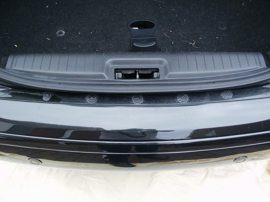 remove the inner insert from the plastic scrivets underneath the vehicle, either side of the towing eye and remove the outer parts 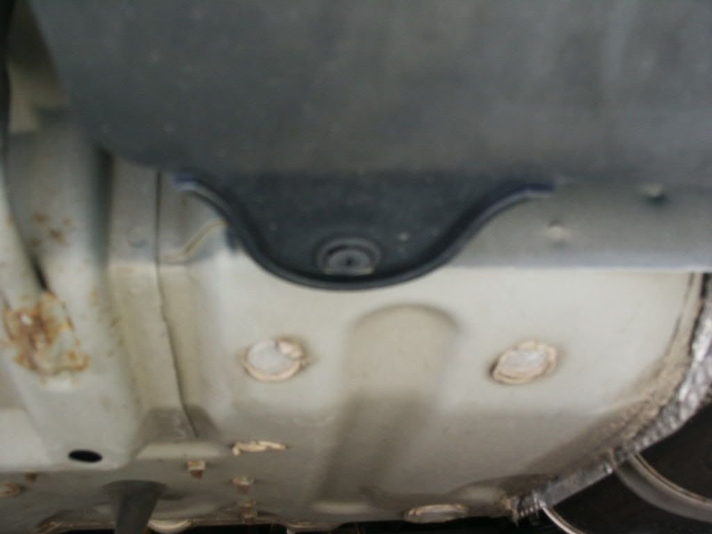 remove the two self tapping screws from underneath the vehicle just behind the rear end of the wheel arch. 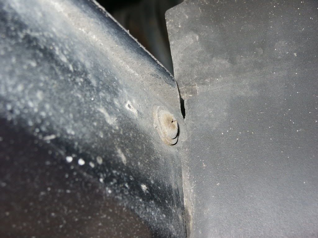 Now, with an assistant, the sides of the rear bumper should be pulled sharply outwards to disengage the bumper from the side mounting clips/rails. The bumper should then be stowed out of the way for the time being. ( dont forget to undo the reversing sensor connector if the sensors are fitted) Having removed the bumper, the pressed aluminium crash rail is exposed. This should then be removed. 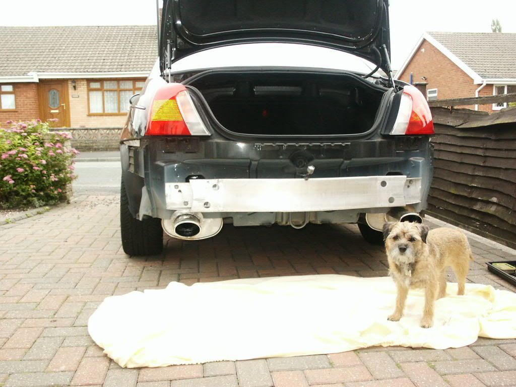 This picture shows a potential rust trap area where the rear chassis box section meets with the crash rail. this has been cleaned and dried and a buttering of waxoyl applied. 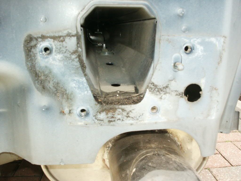 Exhaust removal The exhaust/s require removal to gain access to the underside of the rear chassis rail sections, in order to bolt up the bracket (may not be required for non genuine towing bracket). the front mounting clamp of the exhaust is loosened, and the mounting strap bolt removed (spray with WD40 a few times beforehand to ease their removal). the exhaust can now be pulled clear. If working on axle stands, it may be an idea to support the silencer with a trolley jack, as the are not light. Towing bracket fitment Having prepared the towing bracket by fitting the electrics sockets, the bracket is ready to be offered up to the vehicle. Before doing this there is a metal plate with two large nuts welded to it that fits behind the towing eye. This should be placed in position to prevent swearing afterwards. There are two horns on the bracket with captive nut plates that slide into the rear chassis sections. Once the bracket is held in place then the bolts where the crash rail mounted can be loosely fitted, followed by the two large bolts into the nut plate behind the towing eye, and the bolts and strengthening plates underneath the vehicle. 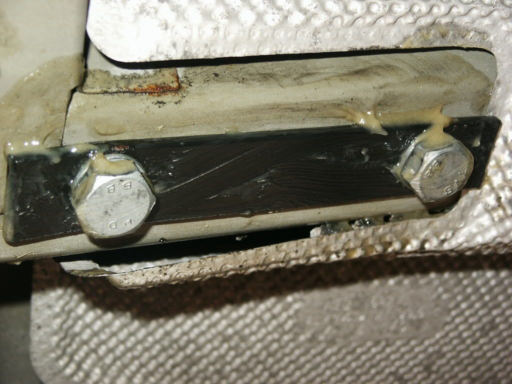 On my vehicle, the exhaust heat shielding required a hole drilling in it to give access to the bolt hole. 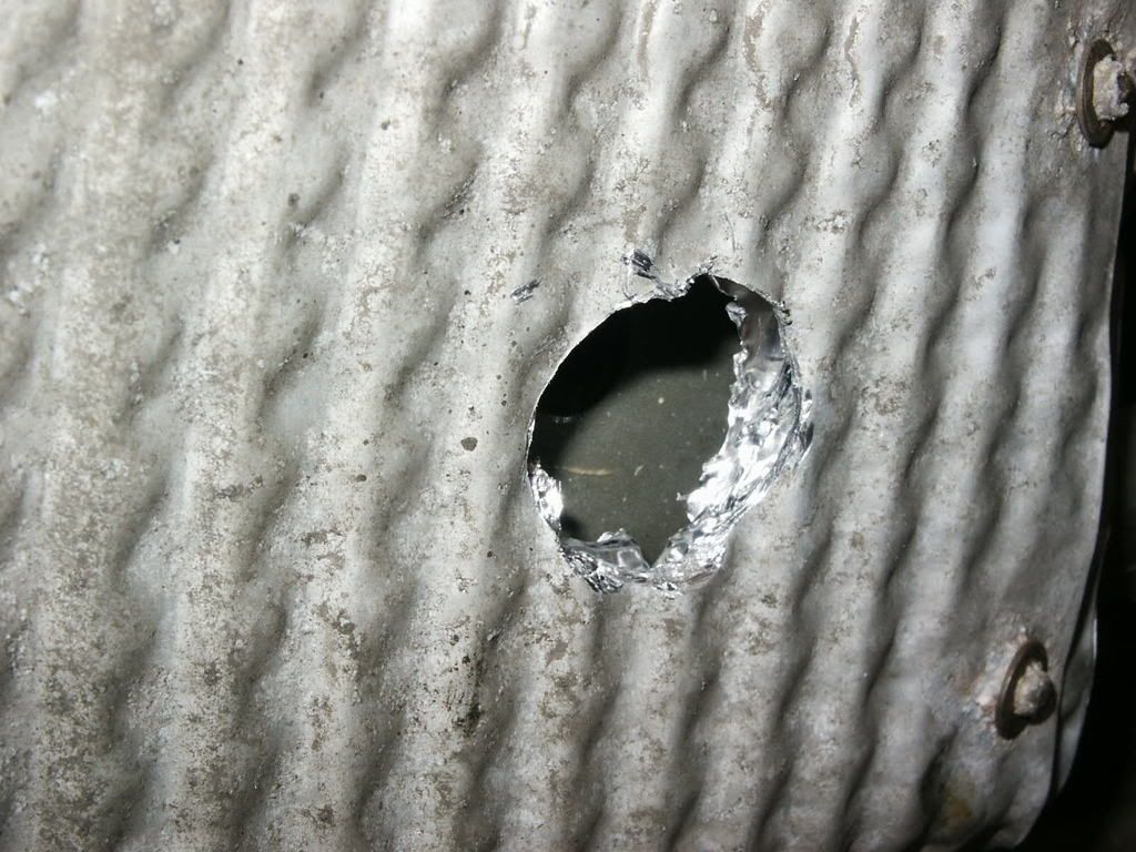 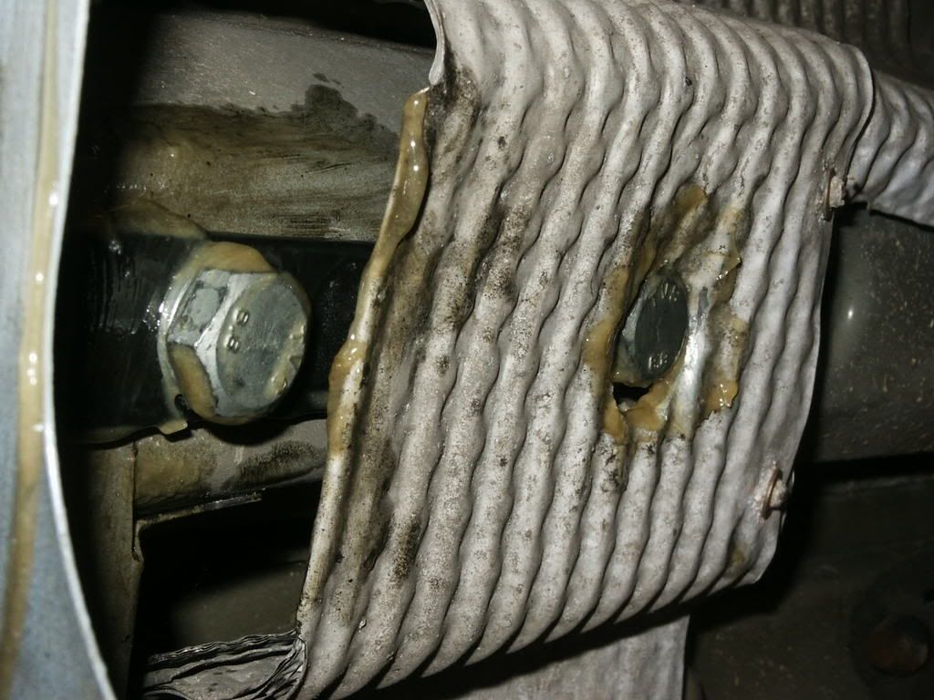 The Bracket fitted . 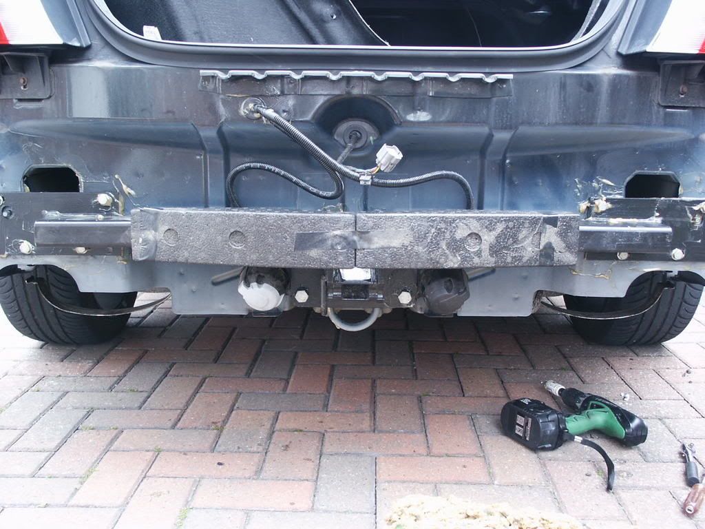 Electrics The electrics kit requires a 27mm hole drilling into the bodywork to gain access into the boot area. the neatest method is to use a hole saw, although if careful it can be chain drilled and filed. protect the edges of the hole with paint or waxoyl or similar. A 13 pin relay is part of the kit, this is affixed to the side of the boot with double sided sticky tape, or I used sticky tie wrap bases and tie wraps. 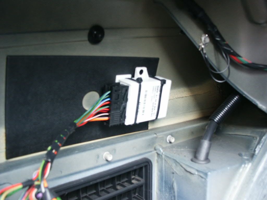 (I also used plenty sticky tie wrap bases to loom the wiring up neatly) wires are provided to run to each rear lamp assembly to pick up their operating signal. these are picked up using scotchlock insulation displacement connectors. nearside 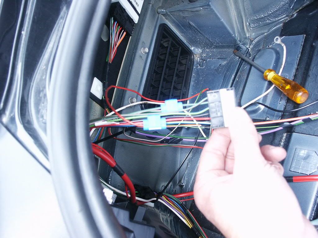 offside 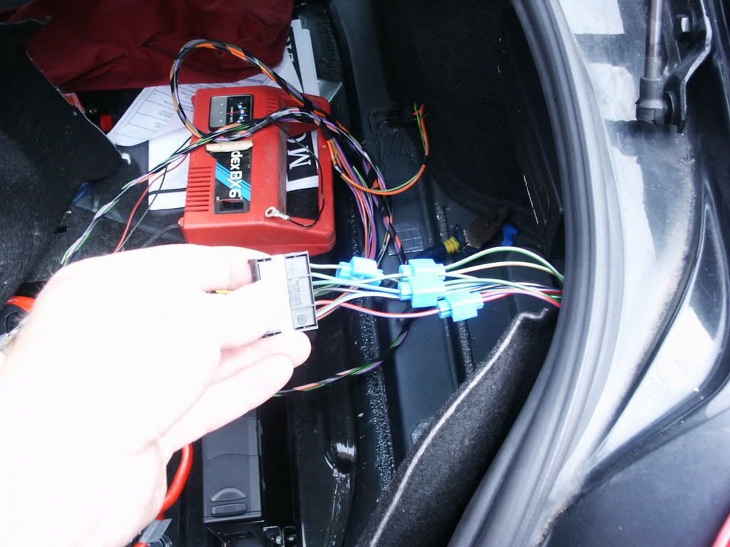 Two earth wires need to be picked up on the earth star point in the boot. The wiring loom then needs to be run to the front of the vehicle, into the passenger compartment fusebox area In order to do this you need to remove the rear seat squab (pull up both sides from the front, then grip the rear and pull rearwards and upwards). nearside front and rear door rubber protectors (spare Christmas tree clips are provided in the kit for when you break yours). Door rubbers. Carpet (remove two grey clips and pull away from the sills) seat belt cover panel Glove box (upper torx fasteners can easily be seen, the lower ones are hidden, lift the velour lining up to expose a double sided adhesive sheet, you will need to poke 3 holes in this to access the fasteners. Fusebox cover (the fasteners at the front of the foot well are unscrewed by sticking a thin screwdriver into one of the three holes and turning- to refit they are pushed on) Front foot well left hand trim panel. Also you will need to remove the offside lower dash trim and the light switch module. by pulling the carpet away you can see where existing looms run to the front of the vehicle, the towing electrics loom can be run to the front of the vehicle with this loom, making sure nothing is catching or chafing. 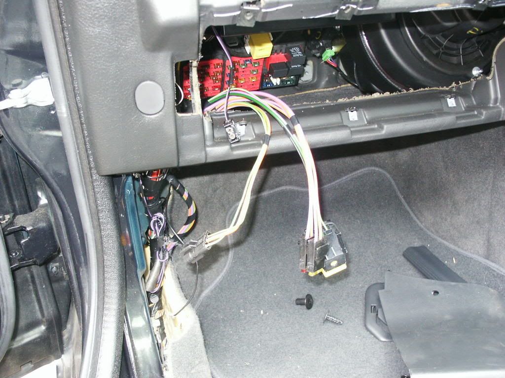 Now things get technical again, and the purpose of the link kit becomes apparent. If you have a copy of RAVE, then print out the relevant accessory fitting instruction for your link kit- or obtain a copy from your supplying dealer. This shows which fuses and connectors are involved. link kit contents 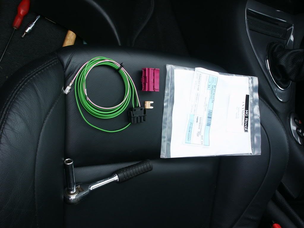 the fusebox is held in by two nuts- remove these and pull the fusebox away from its mounting. carefully noting where they are fitted, remove all the fuses from the left hand bank. once the fuses have been removed, pull away the red plastic frame. this is an anti backout insert that locks the fuses and fuseholer inserts in place. there is a green/pink wire in the link kit with a fuseholder pin on the end. this should be placed in the correct orientation in cavity 15 which responds to fuse 22 (shown pictorially on the instruction sheet). Once this pin has been fitted, replace the red anti backout frame, and push fully home, the fuses can now be replaced, (including the new fuse 22 which is a 5 amp fuse supplied in the link kit). the fusebox can now be refitted. an earth lead is part of the towing kit loom; this should be connected to one of the earth star points in the nearside foot well. now the green wire on the link kit needs routing behind the centre console over to the drivers side, as this plugs into CAVITY 9 of the BLUE connector in the light switch module. unless you have small hands this can be very fiddly- I fed a piece of stout wire through as a fish wire from the drivers side and used this to pull the green wire through. ensure the pin is pushed into the cavity in the correct orientation, a flat bladed jewellers screwdriver can be used to push it fully home, and it will click positively when latched. 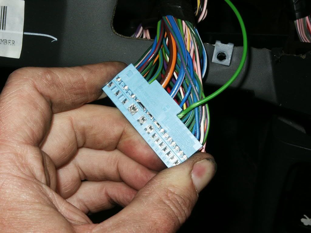 Stowed within the wiring loom going to the fusebox is a stout ORANGE/SLATE wire with a connector pin on it. This will be your feed from the engine bay to the electrics kit. this pin should be inserted into the centre cavity on the black link kit connector. This connector can now be connected up to the towing electrics and all the wiring tie wrapped up neatly out of the way. Now the engine bay fusebox requires removal. the hinged lid should be pulled up and can be removed, and the main feed to the bus bar (BIG RED WIRE) should be disconnected, in order to make it easier removing the fusebox. undo the two posidrive screws at the rear, and the bolt from the front, and lift the fusebox on its loom up out of the engine bay (will only pull up a few inches). the lower cover can then be removed. Within the loom you will see a stowed ORANGE/SLATE wire with a terminal on the end. this terminal clicks into CAVITY 1 of the purple connector housing supplied with the kit. this connector can then be plugged into CONNECTOR 0573 of the fusebox, and the fusebox refitted. 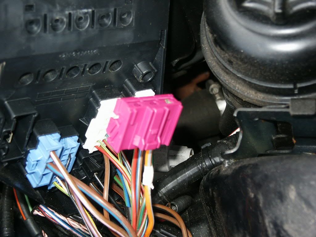 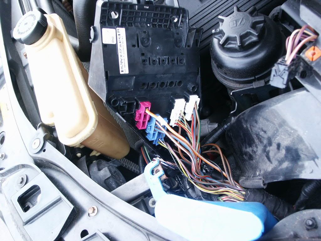 Having done all this, the battery can be reconnected, and the electrics tested against your trailer/caravan (or most caravan dealers have a test box that simulates a caravan being fitted). Once you are satisfied that everything is working the trim, bumper etc can be refitted, note that for the removable bracket the sockets are tucked away underneath the vehicle, and the bumper requires a cut out. A line for the cut out is marked on the inner face of the bumper. I used my 25mm hole saw to make a chain of holes, and then carefully trimmed the excess away with a Stanley knife. 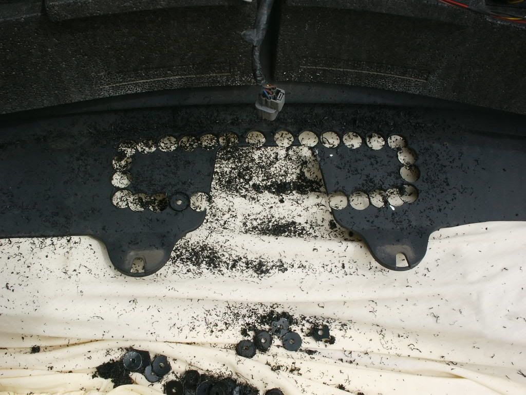 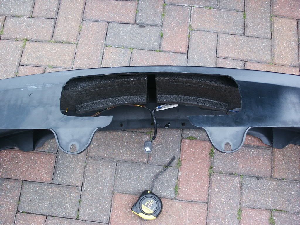
__________________
[SIGPIC][/SIGPIC] Last edited by black olive; 2nd July 2008 at 15:08.. |

|

|
|
1st July 2008, 09:34
|
#2 |
|
This is my second home
ZT 260 SE Twilight and 10 other 75 ZT's :O Join Date: Jan 2007
Location: Conwy NORTH WALES
Posts: 11,094
Thanks: 512
Thanked 1,116 Times in 763 Posts
|
Excellent Steve
I'm surprised an OEM kit relies on those pescy scotch lock connectors though, not my favourite way of connecting conductors!!
__________________
[SIGPIC][/SIGPIC] Newbies do now!! 1. Plenum drains..all 3 or 4 year dependent 2. Cooling fan..All speeds functioning 3. Bonnet cable divider block |
|
|
|
|
1st July 2008, 10:36
|
#3 |
|
I really should get out more.......
260 SE vin 214 ( last mark 1 260 ) Join Date: Dec 2006
Location: Lancashire
Posts: 2,009
Thanks: 1
Thanked 8 Times in 4 Posts
|
Cheers Jules- I concur with you on the use of scotchloks- if the connections were pulling current I would have binned the scotchloks and gone for these
http://www.vehicle-wiring-products.e...insbullets.php but as they are protected from the elements and are providing a low current signal for the relay considered their use to be acceptable.
__________________
[SIGPIC][/SIGPIC] |
|
|
|
|
1st July 2008, 16:27
|
#4 |
|
This is my second home
Volvo C70 Convertible and JZR 3 wheeler Join Date: Nov 2006
Location: Tring, Herts
Posts: 3,960
Thanks: 124
Thanked 173 Times in 124 Posts
|
Whew!!
Looks like it will be a brilliant how-to when WIP is finished. I'm particularly looking forward to seeing the pics. Ironwork installation seems approx the same as my 2nd hand witter (I think it's a witter anyway, as a witter logo was on the towball plastic cover) one, and is very straightforward. But the electrics seem so much more complicated than mine - OK I have an aftermarket trailer flasher warning light, not an OE one in the Instrument cluster, and single socket, not twin, but I do have the multiplex relay protecting the bulb failure circuitry. It was so much simpler to instal, no removing of fuse boxes, and I didn't even have to disconnect the battery as I tapped into an ignition-controlled fuse. The reason for this being that I can't see me wanting to use the towbar electrics without the ignition being on. (Re tapping into the fuse, I used a piggy-back fuseholder, which unfortunately was not very well made, and didn't fit very tightly in the fuse slot. It came loose, disconnecting the rear parking sensors and blind!! With a bit of fettling - ie I bent it slightly - it's now a much tighter fit.) Malcolm
__________________
Only my opinion, obviously, so please dont shoot me if it doesnt match yours! Last edited by baxlin; 2nd July 2008 at 12:08.. |
|
|
|
|
2nd July 2008, 15:14
|
#5 |
|
I really should get out more.......
260 SE vin 214 ( last mark 1 260 ) Join Date: Dec 2006
Location: Lancashire
Posts: 2,009
Thanks: 1
Thanked 8 Times in 4 Posts
|
Right, Ive done- should have taken more pictures of trim removal but its fairly straighforward.
Can someone proof read and post up or PM with any questions, and then it can be locked .
__________________
[SIGPIC][/SIGPIC] |
|
|
|
|
2nd July 2008, 15:39
|
#6 |
|
Banned
- Join Date: Nov 2006
Location: -
Posts: 10,318
Thanks: 0
Thanked 4 Times in 3 Posts
|
Thanks very much Steve. First post now copied and locked in the How-To forums here: http://www.the75andztclub.co.uk/foru...ad.php?t=23097
|
|
|
|
|
14th June 2013, 08:43
|
#7 |
|
Avid contributor
rover 75 tourer Join Date: Nov 2010
Location: birmingham
Posts: 123
Thanks: 107
Thanked 33 Times in 25 Posts
|
hi all have folloewd the above posts and got diagrames but am still lost on this have run wires to fuse box the orange and slate and the two green wires one thin one one thick one have joined up the orange and slate one to engine fuse box and got a 12v supply but where do the two green wires go the thin one has a spade connector with a brown cover and the thick one goes to a blue connector block and the wire splites to a white block with nothing on the other end have tested the grey socket and go power but no charge or fridge supply also where does the link lead go have got it lsm switch the other end goes to to black connector but to what any help please as really stuck as what to do may be i got wrong link lead dont know the car is a 2005 tourer diesel thanks paul
|
|
|
|
|
11th August 2019, 16:56
|
#8 |
|
Newbie
Rover 75 Saloon Join Date: Mar 2016
Location: prague
Posts: 19
Thanks: 2
Thanked 3 Times in 2 Posts
|
hello. can someone help me with a wire diagram?
https://ibb.co/4f1bdR6 https://ibb.co/xjsC3Bc https://ibb.co/xFJBgX4 https://ibb.co/0QmSR72 Last edited by phono; 11th August 2019 at 17:01.. |
|
|
|
|
11th August 2019, 18:32
|
#9 | |
|
This is my second home
Rover 75 Saloon & Tourer Join Date: Sep 2012
Location: Lincoln
Posts: 14,928
Thanks: 1,630
Thanked 3,032 Times in 2,181 Posts
|
Quote:
I cant find it but try asking T-cut or Arctic, I cannot recall which one but they have posted what pins of the BMW relay go to which light. Does your 3rd picture include a parking sensor harness? macafee2 Last edited by macafee2; 11th August 2019 at 18:36.. |
|

|
|
|
11th August 2019, 19:33
|
#10 | |
|
Newbie
Rover 75 Saloon Join Date: Mar 2016
Location: prague
Posts: 19
Thanks: 2
Thanked 3 Times in 2 Posts
|
Quote:
how is acting automatic gearbox when we tow? |
|
|
|
|
 |
|
|


 Linear Mode

