Go Back   The 75 and ZT Owners Club Forums > The 75 and ZT Owners Club Forums > Technical Help Forum
Register FAQ Image Gallery Members List Calendar
Notices

Reply
 
Thread Tools Display Modes
Old 10th May 2022, 14:15   #11
suzublu
This is my second home
 
suzublu's Avatar
 
rover 75 1.8 vvc club se wedgwood blue

Join Date: Aug 2009
Location: Seaton Carew
Posts: 26,912
Thanks: 65
Thanked 7,142 Times in 4,642 Posts
Default

You have to be a subscribed member me old fruit ��

Does this help?

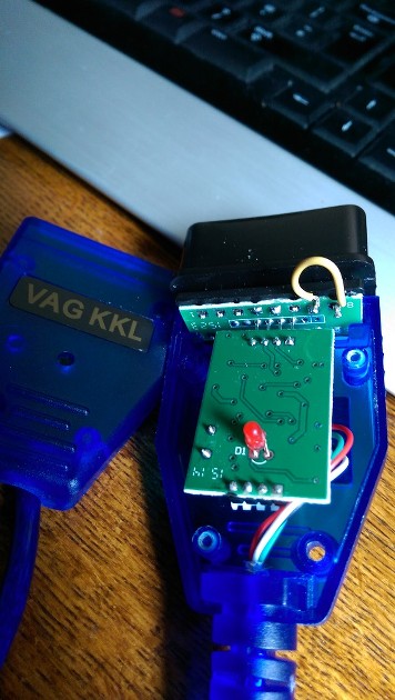
Last edited by suzublu; 10th May 2022 at 14:20..
suzublu is offline   Reply With Quote
Old 10th May 2022, 19:41   #12
grivas
I really should get out more.......
 
grivas's Avatar
 
Rover 75 CDT Club Tourer

Join Date: Nov 2006
Location: Milky Way
Posts: 2,369
Thanks: 105
Thanked 513 Times in 382 Posts
Default

Quote:
Originally Posted by suzublu View Post
You have to be a subscribed member me old fruit ��

Does this help?
Thanks for clarifying the situation, that is unfortunate. The photo is informative but not helpful, my cable has a different arrangement, i was hoping that member Stubie would be able to shed more light on the problem. Thanks.
grivas is offline   Reply With Quote
Old 10th May 2022, 21:03   #13
STUBIE
This is my second home
 
STUBIE's Avatar
 
Back in a Rover

Join Date: Nov 2006
Location: Peterborough
Posts: 4,926
Thanks: 131
Thanked 357 Times in 261 Posts
Default

I am on holiday at the moment so can't provide any details But pins 7 and 8 are on the top right as you look at the pins from the odbc connector plug, I just bridged across with solder

Stubie
STUBIE is offline   Reply With Quote
Old 11th May 2022, 12:02   #14
grivas
I really should get out more.......
 
grivas's Avatar
 
Rover 75 CDT Club Tourer

Join Date: Nov 2006
Location: Milky Way
Posts: 2,369
Thanks: 105
Thanked 513 Times in 382 Posts
Default

Quote:
Originally Posted by STUBIE View Post
I am on holiday at the moment so can't provide any details But pins 7 and 8 are on the top right as you look at the pins from the odbc connector plug, I just bridged across with solder

Stubie
Thank you Stubie, for clarifying, so pin 7&8 are top right hand corner, counting as it were as pin 1 the top left hand corner, and pin 16 as the one at the bottom right row.
Is that correct, these are not soldered to anything?
grivas is offline   Reply With Quote
Old 11th May 2022, 13:06   #15
Atlan
Avid contributor
 
rover 75

Join Date: May 2016
Location: Home
Posts: 203
Thanks: 6
Thanked 99 Times in 70 Posts
Default Diagnostic Socket

This is a picture of the diagnostic socket on the car, from this you should be able to correctly identify pins 7 and 8.

__________________
Illegitimi non carborundum
Atlan is offline   Reply With Quote
Old 11th May 2022, 14:22   #16
STUBIE
This is my second home
 
STUBIE's Avatar
 
Back in a Rover

Join Date: Nov 2006
Location: Peterborough
Posts: 4,926
Thanks: 131
Thanked 357 Times in 261 Posts
Default

Quote:
Originally Posted by grivas View Post
Thank you Stubie, for clarifying, so pin 7&8 are top right hand corner, counting as it were as pin 1 the top left hand corner, and pin 16 as the one at the bottom right row.
Is that correct, these are not soldered to anything?
Yes it looks like they are not attached as mine did but if you connect them together it should work as mine did
STUBIE is offline   Reply With Quote
Reply


Posting Rules
You may not post new threads
You may not post replies
You may not post attachments
You may not edit your posts

BB code is On
Smilies are On
[IMG] code is On
HTML code is Off

Forum Jump


All times are GMT. The time now is 01:09.


Powered by vBulletin® Version 3.8.11
Copyright ©2000 - 2024, vBulletin Solutions Inc.
Copyright © 2006-2023, The Rover 75 & MG ZT Owners Club Ltd