
|
|
|
|
|
|
||
|
|
||
|
|
 27th August 2009, 00:06
|
#1 |
|
NI/ROI RS

ZT-T 190 / 75 Diesel x3 / 6 door limo / 216 Cabby / Rover 25 van Join Date: May 2009
Location: Antrim
Posts: 8,104
Thanks: 299
Thanked 1,046 Times in 568 Posts
|
Maybe your one of the unlucky ones that doesnt have an owners manual and doesnt want to search through the forums (how lazy), so powerbulbs.co.uk has a handy guide that will show you what bulbs you need for your 75/zt if you have normal Halogen lights.
Now to make life even easier for you, ive made a quick photoshop of the information for both cars (which is the same, but still its nice to have).  Hope this is useful to other owners.
__________________
Cheers, Colin Robson Rover Repair on Youtube DISCOUNTED MTEC BRAKES FOR ALL MG ROVER'S Braided hoses, more coating and pad options for 2024 |

|

|
|
17th September 2009, 22:26
|
#2 |
|
This is my second home
Rover75 and Mreg Corsa. Join Date: Nov 2006
Location: Sumweer onat mote o'dust (Sagin)
Posts: 21,754
Thanks: 341
Thanked 3,660 Times in 2,924 Posts
|
I keep this handy:
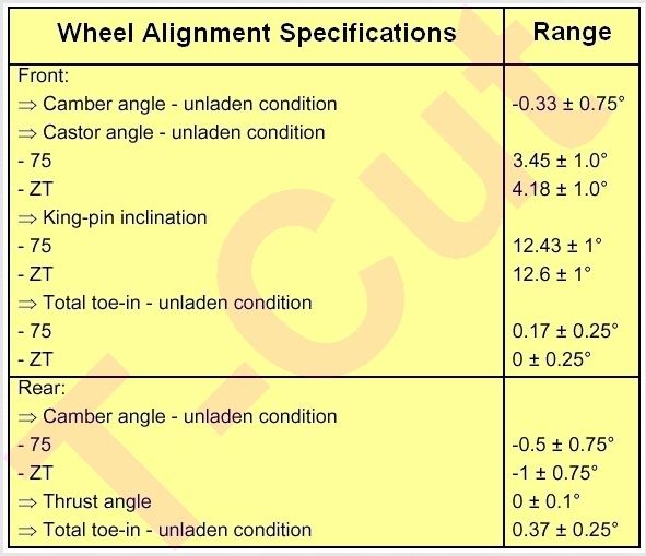 What intrigues me about such specs are the differences between 75 and ZT figures, when they both share identical suspension parts and attachements. How can the King Pin Inclinations differ? How can the Caster Angles differ? I'd like to know what they do to make them different. Are the mounting holes different in the body shells? Edit2: I notice Haynes quotes the above 75 data for all models and averages the King Pin settings. Hmm... EDIT3: (April 2010) I recently discovered that there is a variation in the lower suspension arm (wishbone) rear mounting bushes. The MG models have a different part number from the 75s. This suggests that there will be a variation in certain parameters (don't know which) due to a difference in the positioning of the rear pivot point. This suggests that the 'fits all models' type mounting bushes sold on eBay for example, should be checked out very thoroughly. It could possibly be a reason why many cars seem to suffer tyre edge wear. TC Last edited by T-Cut; 17th March 2014 at 09:07.. |
|
|
|
|
9th November 2009, 01:15
|
#3 |
|
I really should get out more.......
2003 Rover 75 Conn. SE Auto Tourer 131 ps CDTi Join Date: Nov 2006
Location: Bristol
Posts: 2,512
Thanks: 38
Thanked 67 Times in 55 Posts
|
Tried to have a look at handbrake adjustment.
Appears the link in 'the tyre & wheel bible' & 'the brake bible' is the same & only covers wheels & tyres, not brakes. (have scrolled through all 8 pages of posts)
__________________
Rover 75 CDTi SE Connoisseur Tourer (2003) In desirable STARLIGHT SILVER (now restored to it's former glory with all the chrome !) |
|
|
|
|
9th November 2009, 06:17
|
#4 | |
|
Banned
Join Date: Apr 2008
Posts: 237
Thanks: 0
Thanked 1 Time in 1 Post
|
Quote:
Kelvin |
|
|
|
|
|
17th February 2012, 06:48
|
#5 |
|
Posted a thing or two
2005 190 ZT-T SE Join Date: Dec 2010
Location: Dagenham
Posts: 1,242
Thanks: 2
Thanked 10 Times in 9 Posts
|
bumping this post as its getting lost and wondering if some aspects could be filtered into a sticky?
|
|
|
|
|
5th November 2012, 22:16
|
#6 | |
|
This is my second home
None * DROWNED Join Date: Aug 2007
Location: Cardigan
Posts: 33,339
Thanks: 1,257
Thanked 1,664 Times in 1,081 Posts
|
Quote:

__________________
Andrew Ich Dien Problem solving is... lateral thinking SEARCH FIRST ...ASK LATER... Last edited by Dragrad; 6th November 2012 at 20:58.. Reason: typo |
|
|
|
|
|
6th November 2012, 18:42
|
#7 | |
|
This is my second home
ZT400 Join Date: Oct 2006
Location: Ellesmere
Posts: 5,948
Thanks: 0
Thanked 43 Times in 29 Posts
|
Quote:
I guess it went so off topic or because of my resignation from the club after falling foul with a certain couple of now extremely ex management colleagues it got unstuck. Plus a lot is probably out of date now anyway. |
|
|
|
|
|
25th November 2012, 18:10
|
#8 |
|
This is my second home
R75 Saloon. Join Date: Feb 2009
Location: France/or Devon.
Posts: 14,003
Thanks: 3,851
Thanked 2,167 Times in 1,816 Posts
|
Posting this here cos nobody really seems to know what chemical actions take place inside a charged battery as it starts to discharge. So here it is.
Basically lead to lead sulphate and acid to water. Follow the colour scheme. The two plates end up as lead sulphate when the battery is discharged. PbSO4. When recharged the negative plate is pure lead. Pb. The positive plate becomes lead dioxide. PbO2. The red ++ indicates two ions and the blue = indicates two electrons. H2SO4 is the sulphuric acid. H2O is the water. Pb0 is lead oxide. The battery is shown discharging. The direction of the chemical reactions is reversed on charging. A battery must NEVER be left in a discharged state as the lead sulphate crystals on the two plates compact over a period of several months to a solid layer and kill the battery. Charging and discharging keeps this sulphate layer to a minimum and increases the lifespan of the battery. Colvert. ( Look after your battery and it will look after you. Lol ) PS. Click on thumbnail and have a study of it. The colours show how the chemicals combine and what compounds they form. The coloured arrows show the order in which the reactions take place. Last edited by Dragrad; 27th October 2013 at 00:37.. |
|
|
|
|
4th February 2013, 11:32
|
#9 |
|
This is my second home
R75 Saloon. Join Date: Feb 2009
Location: France/or Devon.
Posts: 14,003
Thanks: 3,851
Thanked 2,167 Times in 1,816 Posts
|
http://www.aronline.co.uk/blogs/fact...essay-k-series
(Try number 2. Lol ) Got it, it works this time. lol. When you get there also click on the bit further down the page-----'WHAT MAKES IT TICK'. This gives much more detail about the 1.8 engine development. Colvert. Last edited by COLVERT; 4th February 2013 at 11:44.. |
|
|
|
|
26th July 2013, 07:58
|
#10 |
|
This is my second home
Rover 75 CDT Manual Connoisseur SE, Rover 75 CDT Automatic Connoisseur SE & a Freelander Td4. Join Date: Jul 2009
Location: Hampshire
Posts: 11,578
Thanks: 3,470
Thanked 3,119 Times in 2,247 Posts
|
I modified my CDT to run a single speed fan a few years ago, and noticed that the Rover circuit diagram was incorrect, so drew these diagrams up.
The diesel engines run quite cool so will work fine with a single speed fan in the UK climate, but I wouldn't do this with the petrol engined models, as they need all the cooling they can get. If you do fit a non standard fan the correct rated fuse must be used to protect the circuit. I fitted a 25 amp fuse that was originally used with the donor fan, but of course this may vary. [IMG]  [/IMG] [/IMG] [IMG]  [/IMG] [/IMG][IMG]  [/IMG] [/IMG]Hope this helps. Mike Last edited by Mike Noc; 26th July 2013 at 08:01.. |
|
|
|
 |
|
|


 Hybrid Mode
