

|
||
|
|
||
|
|
||
|
|
#1 |
|
Loves to post
MG ZT-T 190 Join Date: Jul 2014
Location: Penrith
Posts: 441
Thanks: 89
Thanked 69 Times in 56 Posts
|
The other day I was browsing eBay for my wishlist of things, I came across a faulty MK4 Sat Nav drive for a relatively large sum of money but with an offer option.
Having read much about these sat nav drives, I thought I'd make a daft offer. Clearly this has been for sale for some time as I got it half price, which was around Mk3 money. I was naturally very pleased with myself after all, it could just be an input capacitor. Well, the item was shipped at a blistering rate and arrived from Ireland the next day. I spent a good few hours yesterday diagnosing and tracing power around the board, there is a nifty high side power switch controlled by 5V. And initial tests showed the eject button lit up and the power light did nothing. I flipped the board over and saw what was clearly a very small amount of water damage matching with the metal surround in one corner of the board, solder resist appears to be flaking off, and some other nasty corrosion occurring. The components in amongst all this is a 5V regulator and some smoothing caps. I cleaned the board off with a fibre abrasive pencil and checked for shorts and damage. Clearly someone had been here before and had written the drive off as water damaged. 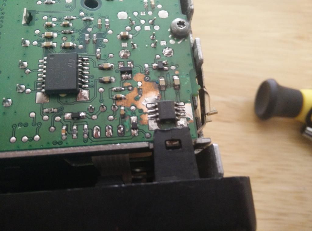 After some more poking around and generally not finding anything despite the corrosion, I soon gave up and reassembled the thing for in car testing. Today, I did some testing...the fun really started then. The drive was soon connected up, I opened up the car door and BMW was plastered on the screen. Hopes were raised, but nothing seemed to happen. 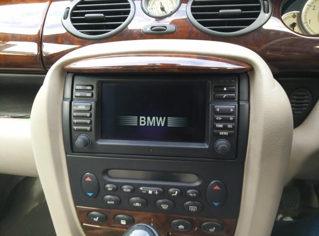 The drive presumably crashed. After a power cycle the screen was taken over by the TV module in typical 80's styling as all the BMW forums suggested would happen (alarmingly similar to the standard Rover Mk3 I thought) 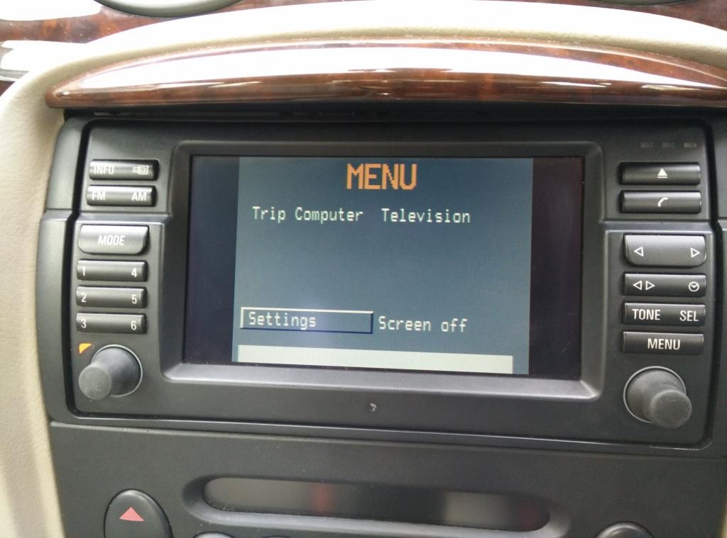 Discs would be taken in and spin for a while then be ejected. Not much seemed to be happening. I retreated inside for some more research and decided I needed to attempt a firmware upgrade. After a while of looking around for the firmware, and buying some blank CDs and DVDs  I had myself a standard V32 update disc, and a couple modified discs with a Rover splash screen just in case. I had myself a standard V32 update disc, and a couple modified discs with a Rover splash screen just in case. To get the car to play ball, I had to put the original Mk3 drive back in and make sure the car saw it, then swap it with the Mk4 (after the Mk3 powered itself down) Once this was done the drive would make one attempt at booting up, in went a disc and low and behold an update screen came up. 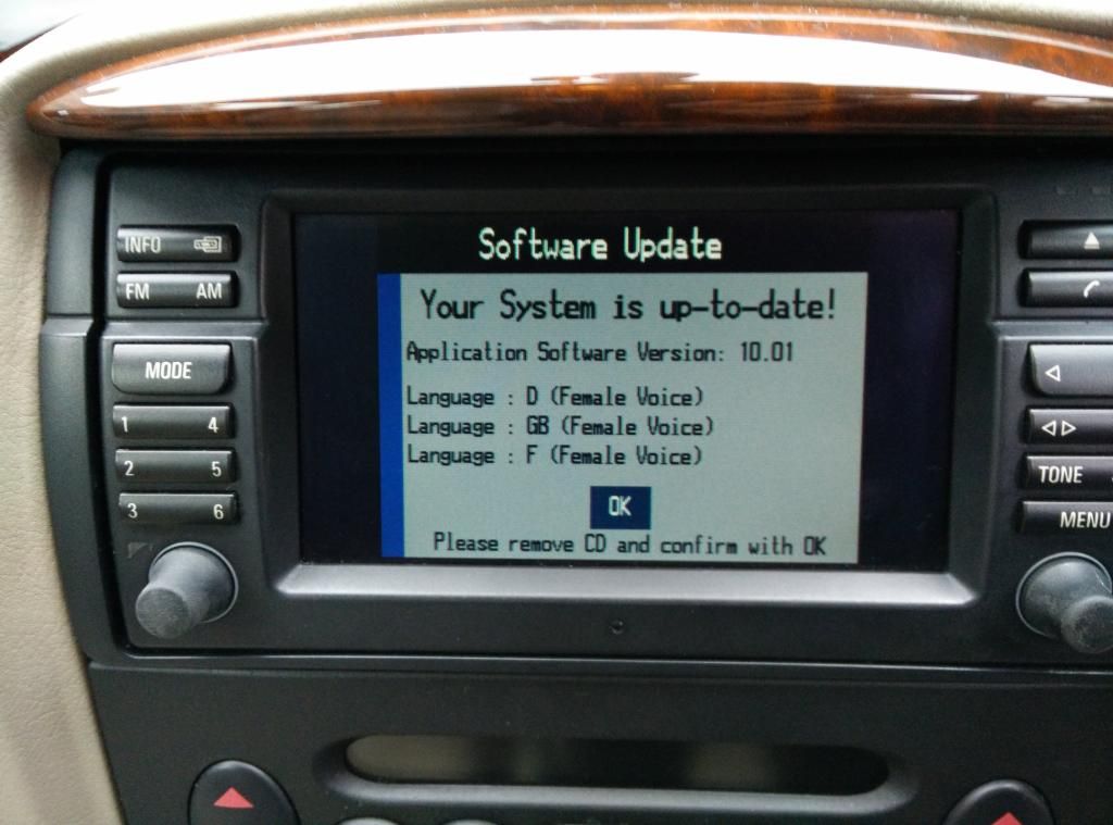 Yet another hope rising result only to bring me back down to Earth with another disappointment.  My drive already has this software version. Hmm. Back to the drawing board... My drive already has this software version. Hmm. Back to the drawing board...Quick as a flash, (at least I bought the bigger pack of CDs) a V29 update disc in hand, and the musical sat nav drives completed. The downgrade went perfectly. Here I noticed the real problem...the screen comes up remove disc and press ok to confirm. 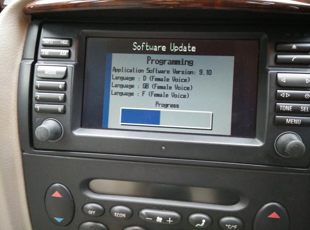 No matter what I pressed or how long I pressed it, ok would not be confirmed. Now, how likely is it that this last piece of the puzzle gets this drive out of its purgatory state just so happens to be impossible. I have an incline as to what the problem may be. Many drives would have been scrapped long before now, but no, I am now determined  . . Just to be sure, I put the V32 disc back in after the usual jiggery pokery and hey presto loaded the software back just fine, but still couldn't confirm with an OK. I have a sneaky suspicion [read hope] there is a problem with the IBUS connection hence a button press can't work, and the other systems can't see that nav drive. I sincerely hope there is a discrete transceiver or something to interface with the bus I can get at, or at least test. Because if there isn't, this could well be the end of the road for this board. The board is very well designed, and the extreme last hope is an unpopulated connector with a few lines leading off a serial chip...must be a debug or hopefully a program port. For now, the saga continues. Here are a couple more photos of around the board, and under the shielding. 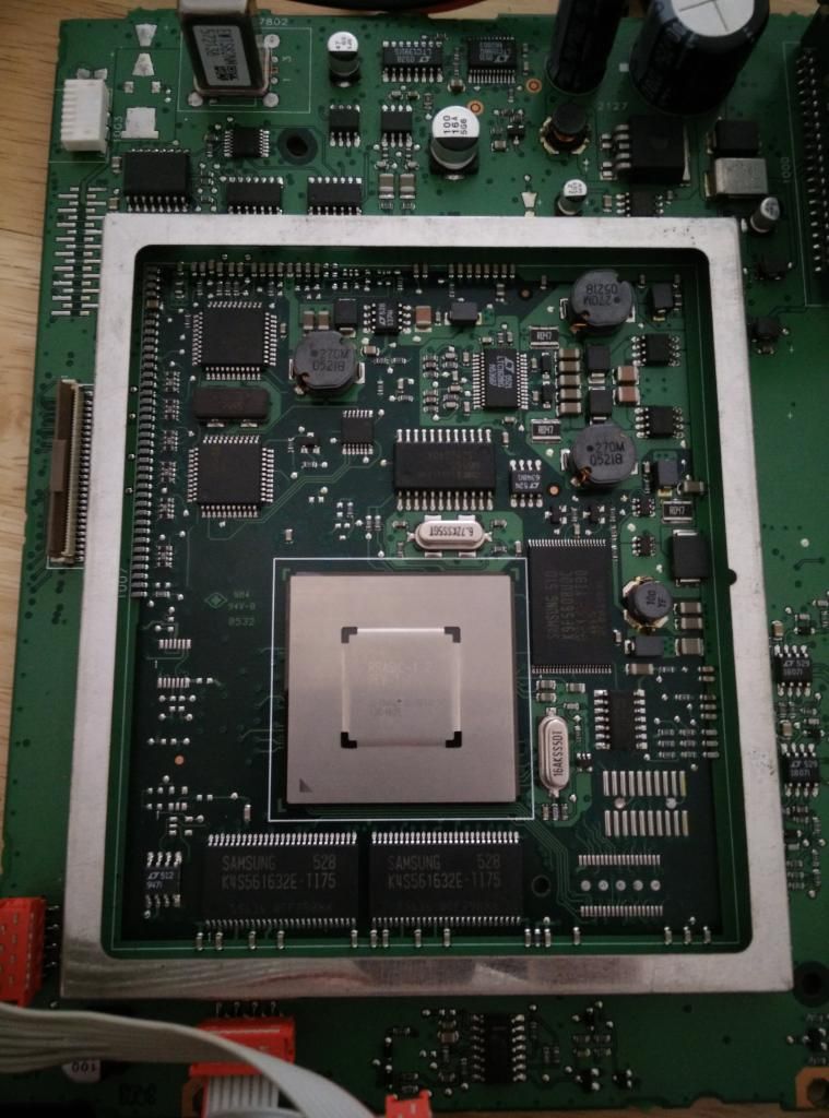 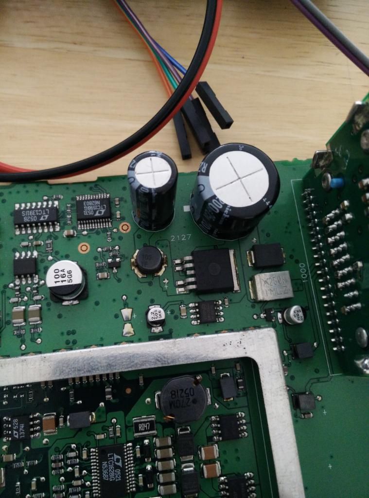 
__________________
ZT-T 190 |
|
|

|
|
|
#2 |
|
Vis Whiz
Rover 75 2.5 auto Saloon Join Date: Jun 2007
Location: LEEDS
Posts: 20,586
Thanks: 2,057
Thanked 3,056 Times in 1,621 Posts
|
Fascinating, good luck with the repair

__________________
Dave...  Lost a few stones  and a Gall Bladder and part of a bile duct and all of my dignity in the suppository incident and a Gall Bladder and part of a bile duct and all of my dignity in the suppository incident 
|
|
|

|
|
|
#3 |
|
Been absent for a while…
Rover 75 Tourer, Classic mini Cooper S, Abarth 595 competizione, MG TF and a Hyundai Tucson PHEV Join Date: Feb 2007
Location: Cumbria
Posts: 13,065
Thanks: 1,033
Thanked 1,686 Times in 1,040 Posts
|
Reading this and really hoping for a happy ending, good luck

__________________
.................................................  'Marmite' Possibly one of the most famous 75 tourers produced! left the production line as the last of only Three Rover 75 tourers produced in Trophy Yellow. 48 hours later Longbridge closed. The last sold ordered 75 Tourer. Paid for by the Phoenix Four and handed over by John Towers to the Warwickshire Northampton Air ambulance service as a Rapid Response vehicle |
|
|

|
|
|
#4 |
|
Loves to post
MG ZT-T 190 Join Date: Jul 2014
Location: Penrith
Posts: 441
Thanks: 89
Thanked 69 Times in 56 Posts
|
Ok a small but important update. I just so happened upon a thread involving someone elses attempts at repairing this exact drive earlier in January on a Range Rover site. He has replaced the 5V LE50 chip, but got stuck with the apparently missing component in the centre of all that mess.
One side is ground and the other is 12V, so I can logically assume this to be a smoothing capacitor. I followed the via to other side of the board, and well, just some unpopulated larger capacitors etc. This is obviously where the problems have occurred shorting 12V around the underside of the board. Ignoring that for the time being, I thought I would do a swipe over and check all the resistors weren't short or open. Low and behold there was one 472 resistor totally open circuit. I traced the resistor to be the positive of the power LED. Bodged in one of my through hole 4.7k resistors and now the power LED works. Hurray. I have also spent an age following the Ibus across the board. Only to find two ELMOS 10020B chips, to find the Datasheet search ELMOS E910.05. This is then put through a buffer chip and gets lost towards the main ASIC. With any luck I should be able to find the problem when I get back to testing the thing if I haven't miraculously solved it with a working LED. I really should make up a bench testing loom or something. Life would be much easier.
__________________
ZT-T 190 |
|
|

|
|
|
#5 |
|
Newbie
None Join Date: Mar 2015
Location: Glasgow
Posts: 6
Thanks: 0
Thanked 0 Times in 0 Posts
|
Hi...just stumbled across this and couldn't believe what I saw! I was the last person I think to have a go at this and I think you found my thread on the ffrr site. I'd bought it as a supposedly dead unit for £80 but when it was sent to me it had the LE50 chip burned out on the bottom and the 5v out pin was gone. It had heat damage on the board around it. I cleaned it up, and replaced the LE50 chip thinking it was worth a go and I think that caused the eject light to start working.
Anyhow it didn't so I stripped the unit and found that someone quite careless had been inside and had damaged the flexi from the main board to the front board with the lights and eject button. I trimmed this to make it work but the flexi to the main board from the DVD drive was also damaged. I trimmed this too and the drive started to work. At this stage the chap agreed to take the unit back and give me another faulty unit because it wasn't described as already having repairs attempted. I think the unit you are repairing is worth fixing as the drive was ok. Have you tried holding the eject button to see it if it will power up? I've got some good mk4's if you want photos of the areas as I'd be interested to see if you can fix it. The burn out was probably caused by a smoothing cap shorting but I'm not sure it has damaged anything else. Good luck cheers James |
|
|

|
|
|
#6 |
|
Loves to post
MG ZT-T 190 Join Date: Jul 2014
Location: Penrith
Posts: 441
Thanks: 89
Thanked 69 Times in 56 Posts
|
The only thing I have found failed is the 4.7k resistor for the power LED. But as I got the drive to actually boot and run a software update, the only thing to check now is the ibus is getting where it is meant to be.
With any luck I will get it working, I was worrying about it being a software problem. Some photos of the underside of the board would be great, I was thinking I'll put a smoothing capacitor back in, but I really can't see a reason. There must be a good one, as it is truly squeezed in and vias aren't cheap. I have a couple more traces to follow, I suspect the UART chip is also at fault. But I will check that in good time. I think I got it cheap at £65. The seller was certainly in a rush to get it to me.
__________________
ZT-T 190 |
|
|

|
|
|
#7 |
|
Newbie
None Join Date: Mar 2015
Location: Glasgow
Posts: 6
Thanks: 0
Thanked 0 Times in 0 Posts
|
Yes the main drive and other parts are worth £65 really.
You've done a lot more diagnosis than I did on the board. I was offered an easier repair so took it! The ibus must be somewhat working on the board as it is getting the message to power on when you open the car door. Otherwise this would not happen. Do you have any idea why it has 2 serial UART chips? I have another MK4 that has a problem in the same region on the board. It was caused by water damage and basically it will only boot up when you hold the eject button so wont power from the cars ibus command. It also dies instantly when the eject button is released but it will take ibus commands from the head unit when powered up. Do you think one of the UART chips is to listen for power commands and the other is for the main processor to get the commands such as ok from the screen controls. I guess you could swap them to check, or see which one has power when the unit is asleep. I'll spend some time on this soon as I need to figure out how it works. Its interesting as none of the normal repairers would touch something like this! |
|
|

|
|
|
#8 | |
|
Loves to post
MG ZT-T 190 Join Date: Jul 2014
Location: Penrith
Posts: 441
Thanks: 89
Thanked 69 Times in 56 Posts
|
Quote:
There is a high side power switch near the boards filter capacitors. Check the enable pin (possibly pin 2 from memory, check to be sure) is getting the correct 5V to turn the system on. If you have to hold the eject button, that could suggest a 5V power or ground problem. I suspect there are two UART chips because the GPS has Tx and Rx output/input which may go to the traffic master system if fitted. Not entirely sure. Everything seems to be doubled up, but I think the power down is handled by a lack of bus activity. I will be able to better test now the power LED works. I saw a challenge and if I get it working, I will start repairing them more often.
__________________
ZT-T 190 |
|
|
|

|
|
|
#9 | |
|
Moderator
MG-ZTT Join Date: Mar 2007
Location: Ware, Herts
Posts: 19,798
Thanks: 161
Thanked 1,249 Times in 1,036 Posts
|
Quote:
__________________
David  Impecunity is the mother of ingenuity Useful how to's for common problems Car Of The Month Jan 2014 [SatNav Power Down] [Coolant Level] [SatNav Repair] [Diesel Non Starting] [Paint Codes] [Rear Light Seals] [Reversing Light Switch] [Bleeding Brakes][Sunroof Drain] [Early ZT's][Instrument Pack Diagnostics][ATC Diagnostics] |
|
|
|

|
|
|
#10 |
|
Newbie
None Join Date: Mar 2015
Location: Glasgow
Posts: 6
Thanks: 0
Thanked 0 Times in 0 Posts
|
Yes I was thinking about it last night and thought it may befor the GPS send and return for the other chip. I'm lucky that I've got a known good system here, its just getting the time to test!
Or at least I had a working system...just accidently shorted the centre pin on the power switch BTS442E2 to pin 2 by slipping with the multimeter and now its totally dead...pin 2 was ground at the time. Hoping its the overload protection but not sure. |
|
|

|
 |
| Thread Tools | |
| Display Modes | |
|
|