
|
|
|
|
|
|
||
|
|
||
 31st December 2014, 15:17
|
#1 |
|
Gets stuck in
ROVER 75 CDT CLUB SE 02 Join Date: Aug 2009
Location: Kent
Posts: 658
Thanks: 30
Thanked 141 Times in 87 Posts
|
This simplified diagram shows the relationship between the CDT charging circuit and the Webasto Fuel Burning heater (FBH) where fitted, and it's dependency on the alternator for it to run with the basic factory set up, no remote , ambient temperature switching only.
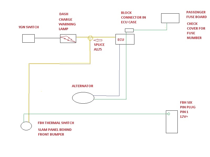 This is how it functions, all components functioning correctly. When the ign key is turned it feeds the charge lamp on the dash 12v to illuminate it. At the same time 12v is sent via the fuse board to the alternator to excite it (pre charge it) from the passenger side fuse board. (Green wire. to alternator). When the key is turned to position 2 (start pos ) released and the engine runs, the alternator now generating it's own 12v supply, feeds via it's Blue wire, 12v to the ECU, which in turn ,via the Brown /Yellow wire from it, feeds 12v back to the charge lamp diode extinguishing it, thus confirming alternator function. This connection Brown/ Yellow wire between the ECU and the dash is spliced (A125) in the loom. The 12v that was feeding the battery charge lamp is now shunted down this splice to the FBH thermal switch . If the ambient temperature is +5 degrees C or less, the thermal switch activates, sending 12v+ from the thermal switch via the Green / White wire to pin no 1 of the FBH six pin plug. This is the start control voltage for the FBH, and on receiving it the FBH will go into it's start cycle and , if all is well, will fire up. The FBH continues to function until the water temperature in the FBH reaches 76 degrees, when it goes into standby mode, ready to re activate if the two control temperatures air , water demand it. This cycle will repeat as long as the air temperature and water temperature are within these boundaries. At any time the engine is stopped, the alternator will no longer be feeding the FBH voltage, so it enters it's shut down phase, to eventually switch off. Hope this is of some use. Happy New Year to all members,old and new. Snagger
__________________
How to remove CDT alternator from top & side :- http://www.the75andztclub.co.uk/foru...d.php?t=199608 Battery charge light problems on a diesel ? http://www.the75andztclub.co.uk/foru...3&postcount=64 Diesel charging FBH voltage supply diagram http://www.the75andztclub.co.uk/foru...ght=cdt+charge How to identify voltage regulator type diesel http://www.the75andztclub.co.uk/foru...56&postcount=3 |

|

|
|
5th January 2015, 15:00
|
#2 | |
|
Newbie
Rover 75 Saloon Join Date: Dec 2014
Location: Birmingham
Posts: 17
Thanks: 0
Thanked 0 Times in 0 Posts
|
Quote:
Is this also for the 2001/06/ date of manufacture model as well |
|
|
|
|
|
5th January 2015, 15:06
|
#3 |
|
Newbie
Rover 75 Saloon Join Date: Dec 2014
Location: Birmingham
Posts: 17
Thanks: 0
Thanked 0 Times in 0 Posts
|
Hope that you can reply a.a.s.p to this post
|
|
|
|
|
5th January 2015, 16:14
|
#4 |
|
I really should get out more.......
Now Other Manufacturer Join Date: Nov 2006
Location: Co. Kerry
Posts: 2,786
Thanks: 16
Thanked 310 Times in 283 Posts
|
The alternator feed to the FBH is the same for all years.
|
|
|
|
|
5th January 2015, 19:13
|
#5 | |
|
Gets stuck in
ROVER 75 CDT CLUB SE 02 Join Date: Aug 2009
Location: Kent
Posts: 658
Thanks: 30
Thanked 141 Times in 87 Posts
|
Quote:
This applies to the ZT as well, btw. Snagger.
__________________
How to remove CDT alternator from top & side :- http://www.the75andztclub.co.uk/foru...d.php?t=199608 Battery charge light problems on a diesel ? http://www.the75andztclub.co.uk/foru...3&postcount=64 Diesel charging FBH voltage supply diagram http://www.the75andztclub.co.uk/foru...ght=cdt+charge How to identify voltage regulator type diesel http://www.the75andztclub.co.uk/foru...56&postcount=3 |
|
|
|
|
|
4th March 2015, 15:09
|
#6 |
|
Newbie
Rover 75 Tourer Join Date: Mar 2015
Location: Toronto
Posts: 1
Thanks: 0
Thanked 0 Times in 0 Posts
|
I was wondering if could find out if this could also be useful for a ’03. I have been trying to figure out these wire connections but I could just never get around to doing that. I know the alternator is connected to the ECU, the same way but I’m not so sure about other connections. Could someone please upload some wiring information of ‘03+ models too?
smt pcb Last edited by danilo; 11th March 2015 at 21:15.. |
|
|
|
|
19th September 2020, 21:04
|
#7 |
|
Give to Learn

Freelander 2 Join Date: Aug 2010
Location: West Midlands
Posts: 18,700
Thanks: 1,155
Thanked 6,407 Times in 3,874 Posts
|
Hi Ron.
Excellent thread mush appreciated 
__________________
Arctic Givology Learn to Give Everything is Achievable  ad altiora tendo. Check out our Nano meet dates http://www.midlandsnanomeets.co.uk/ http://www.the75andztclub.co.uk/index.php?thepage=howto " You do the work , we supply the expertise " |

|
|
 |
|
|


 Linear Mode

