
|
|
|
|
|
|
||
|
|
||
 25th October 2013, 15:39
|
#1 |
|
This is my second home
Rover 75 CDT-2001 Join Date: Jan 2009
Location: Wrexham, North Wales
Posts: 3,606
Thanks: 195
Thanked 606 Times in 501 Posts
|
Thanks to the excellent suggestion from Mike Noc, I can confirm that it is possible to replace alternator Brushes with the alternator left on the car, and here are a few of the steps I followed for my 2001 CDT Alternator YLE102500 (2001 Valeo model)
All done from the top of the engine bay, I didn't remove the undertray today as Mike had suggested because the yard was very wet and I didn't fancy scraping around in the wet, but it may help you to see what you are doing but the principles will be the same as my way. Start by disconnecting the Battery. 1. Remove engine cover 2. Remove air intake duct (This helps you get your arms in at the right angle for removing bolts on the alternator) 3. Remove the single bolt securing the top of the dip stick tube (This just helps you get a long handled socket driver in at the right angle for one or two of the bolts) 4. Using a long flat driver, pull up the retaining wire clip an remove it. keep a finger on it to save it pinging off in to the depths. 5. Remove the small 3 pin connector. From what I've learned the connector is a 3 pin one, but only 2 pins have wires in them. The alternator has 3 pins on in with this model. Dont know what the un-used pin does. But this answers why Rimmers can offer the later 2 pin version as an alternative now. 6. Using a 13mm socket on a driver, (I used a 1/4 drive one) remove the brass nut holding the thick black supply cable. Remove the cable from the alternator and lodge it out of the way until time to refit. 7. You are now looking for 3 8mm brass nuts that hold the alternator rear cover on DSCN0164.JPG This picture shows the alternator after removing the 3 nuts and the cover. The 3 nuts are the one above the big supply stud in between the 3 pin connector and the stud, one almost vertically below the big stud near the bottom, and one parallel with that on on the right hand side. The other ones only become visible after removing the cover. 8. With those 3 nuts removed you can just wriggle the cover over the studs and out of the engine bay. If like mine it will be caked in thick black oil. 9. To understand the next bit take a look at this link for a brand new Voltage Regulator to fit this particular model http://www.vehicleelectricsshop.co.u...BMW_ROVER.html   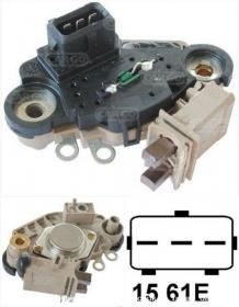 You see the 2 small ring tabs. Then the 2 bigger metal washers at each side. So first remove 2 more 8mm nuts from either side of the regulator. 10. Next you need to remove what looks like a black foam rubber gunge which is covering 2 small 7mm brass screws securing the 2 small ring tabs. It goes without saying to make sure you dont drop any of these screws or nuts. 11. With these removed, the regulator will now pull away from the alternator and can be removed to a workbench for repair. 12. Next inspect the brushes. Mine were badly worn. here is a picture of the old and the new. DSCN0171.JPG One Brush still had a little life left in it, but the other had disintegrated at the end. New ones were 4 times longer, purchased from here: http://www.jcrsupplies.co.uk/product..._REF_5221.html Arrived very next day for about £6 including delivery. 13. I drilled a small 2mm hole through the end of the Brush terminal and the old brushes just fall out. There is a small black Brush cover holding them in at this point which with a little encouragement you can slide off the regulator. It looks fragile so be careful with it. 14. With the old brushes out, be careful not to lose the pressure springs then thread the copper wires for the new brushes back through the 2mm hole you drilled, then I filed a slight groove in the terminal post and wrapped the wires tightly around it before soldering both brushes on to the posts, so they have a firm solder joint and also a mechanical fix. 15. Now go back to the car and clean up the slip rings. Mine were caked with the disintegrated old brush, and I brushed this off with a small paint brush. 16. Now refit everything in reverse order to removal. The Brushes can be tricky to get started, as they protrude under pressure of the spring and need to be gently pushed back in with a small driver until you get the regulator module back in position, but when you try it you'll see what you need to do. My slip rings had grooves in them but the new brushes fitted perfectly in to them, and so I hope will give me a reasonable service life yet. Now that I know exactly where the bolts are, and how it comes apart I reckon i could do the job in just over 1 hour next time. What I also learned doing this job is that at least the full regulator module is available should it become necessary. As I said at the start, if you were to take the engine undertray off, and go at this job from below with a decent set of ramps you may find access easier, but not what I wanted on a soaking wet yard. I hope this will both encourage others with Brush failure, and at least confirm that it is possible in-situ avoiding the need for belt removal and additional expense of 24mm ring spanners etc, which I don't have to hand and would have needed to buy one from Halfords at £9.99 !!! The downside to doing this in such a cramped space was opportunity for photo taking was pretty limited. P.S. Mike Noc - I owe you one ! Last edited by Dragrad; 31st July 2014 at 00:24.. Reason: Thumbnails enlarged - Pic from link added |

|

|
|
|


 Threaded Mode